Introduction
General Introduction
What is Arducam V3Link Camera Solution?
Arducam V3Link camera solution is developed and designed for high-speed data transfer with multi-camera connected. Arducam consistently collaborates with Texas Instrument’s engineering team to provide you with the most adaptable, on-demand V3Link camera systems for various industrial applications.
Arducam has created a versatile and cost-effective camera solution based on TI V3Link SerDes. Breaking free from camera bundles, we opted for a radically different camera solution which is flexible and adaptable.
About TI V3Link
TI V3Link is a multi-protocol physical layer technology, an industrial variant of FPD-Link III that aggregates data from different industry standard protocols and transmits it over coaxial or twisted pair cables.
It acts as a bridge between protocol-based data interfaces to transmit high-bandwidth data over short distances, and it can also act as a data converter in case the source interface does not match the synchronization interface.
TI V3Link SerDes
TI V3Link SerDes currently has two types of integrated chips, the serializers for high-speed bidirectional data transmission and matching multi-functional sensor hubs for accepting data streams.
Through the combined use of V3Link serializers and V3Link deserializer, high-speed transmission of multi-channel data from multiple sensors can be achieved. Data is received and aggregated into MIPI CSI-2 standard compliant outputs for interconnection with downstream processors.
Features
-
One for All: Compatible with more than 100+ off-the-shelf camera module series, covering various resolutions, lens types, sensors and shutter types, etc. You can use it with any Arducam MIPI CSI-2 camera.
-
Flexible and ultra-long range: Provides up to 15 meters of high-frequency stable cable connection on up to 4 camera channels. Enables smaller footprint and flexible deployment.
-
Wide applicability & low development cost: Freely create a synchronous 4-channel vision system, suitable for various applications such as automotive, surveillance, medical, industrial imaging, etc., effectively reducing your costs.
-
Channel switching, independent control: Supports arbitrary switching of four channels. Up to four cameras could be connected, all supporting high-frequency signal transmission and independent control.
-
Highly flexible customization: Customizable in Every Way for Any Platform. Supports diversified customization of various sensors, lenses, carrier boards, housings, embedded development platforms, operating systems, project types, etc.
Data Transfer Process
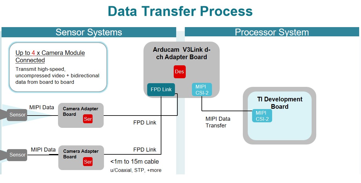
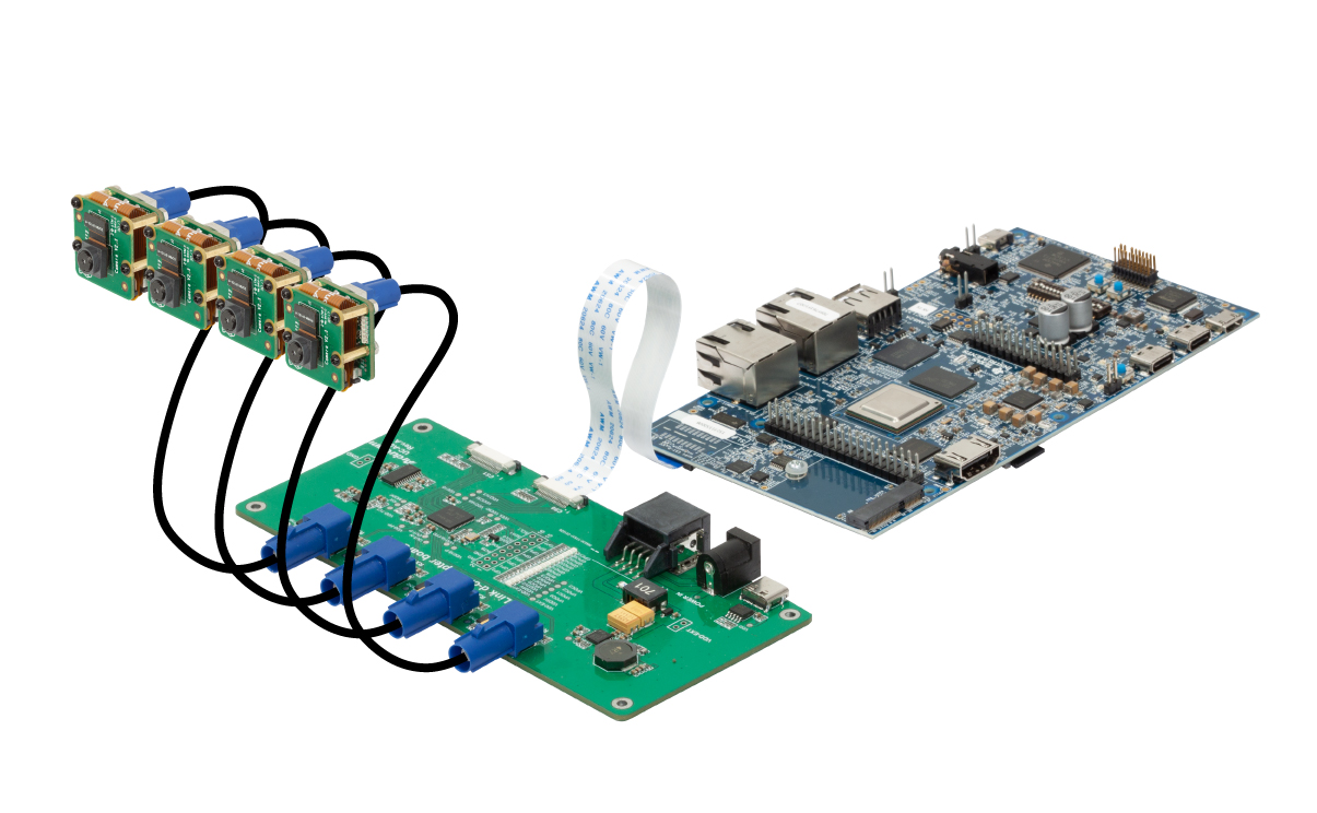
The Arducam V3Link camera solution consists of two pieces of hardware, including an Arducam V3Link d-ch breakout board for connecting to a TI development board and integrating the TI TDES960 deserializer, and an Arducam V3Link d-ch breakout board for connecting to the camera module and integrating the TI TSER953 serializer. Arducam V3Link camera adapter board.
The data is transmitted to the serializer on the camera adapter board through the MIPI CSI-2 interface, and then transmitted to the deserializer on the d-ch adapter board through the high-frequency transmission channel of the FPD Link coaxial cable. The deserializer collects the data output by each serializer and transmits to the host processor through the MIPI CSI-2 interface to complete the data transmission process.
Specification
| Specification | |
|---|---|
| Arducam V3Link d-ch adapter board | |
| Extension Range | < 1m to 15m* |
| Number of Supported Sensors | Up to 4 sensors |
| Data Transfer Protocol | MIPI CSI-2 v1.3 |
| MIPI Port Type | 2 x MIPI CSI-2 Output Ports |
| I2C Rate | Dual I2C Ports, up to 1 Mbps |
| Transmission Cable | FPD Link(Power over-Coax (PoC)) |
| Arducam V3Link camera adapter board | |
| Power Supply | Single 1.8V |
| Connector | MIPI CSI-2 |
| MIPI Lane | 2-Lane |
| Transmission Cable | Power-over-Coax (PoC) compatible transceiver |
| Power Consumption | Low (0.28 W typical) power consumption |
| Operating Temperature | –20℃ to +85℃ |
< 1m to 15m*: The maximum extension range depends on the coax you are using.
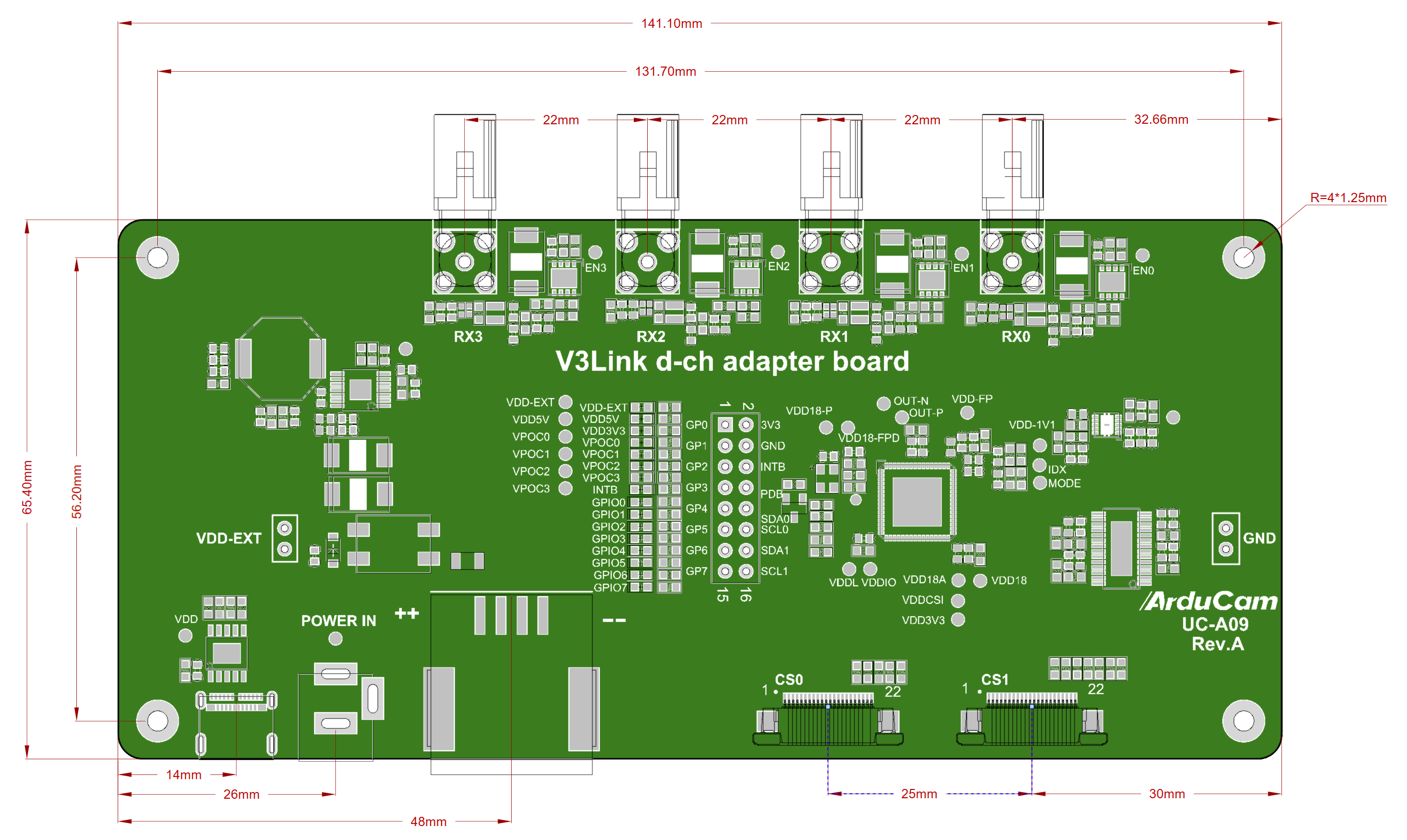
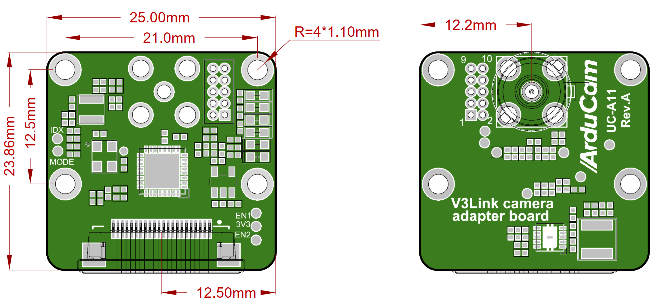
Dimension
- V3Link d-ch Adapter Board
- V3Link Camera Adapter Board
Supported Sensors
Tip
Currently, TI official kernel driver only supports the V3Link camera extension solution for Arducam IMX219 camera series. The subsequent adaptation and development processes for other cameras will continue to be updated.
| Sensor | Resolution | Sensor Brand |
|---|---|---|
| IMX219 | 8MP | SONY |
Product
| Product Image | SKU | Resolution | Sensor | Extension Cable | Extension Range | Focus Type | Field of View(DxHxV) | IR Sensitivity | Peking Current |
|---|---|---|---|---|---|---|---|---|---|
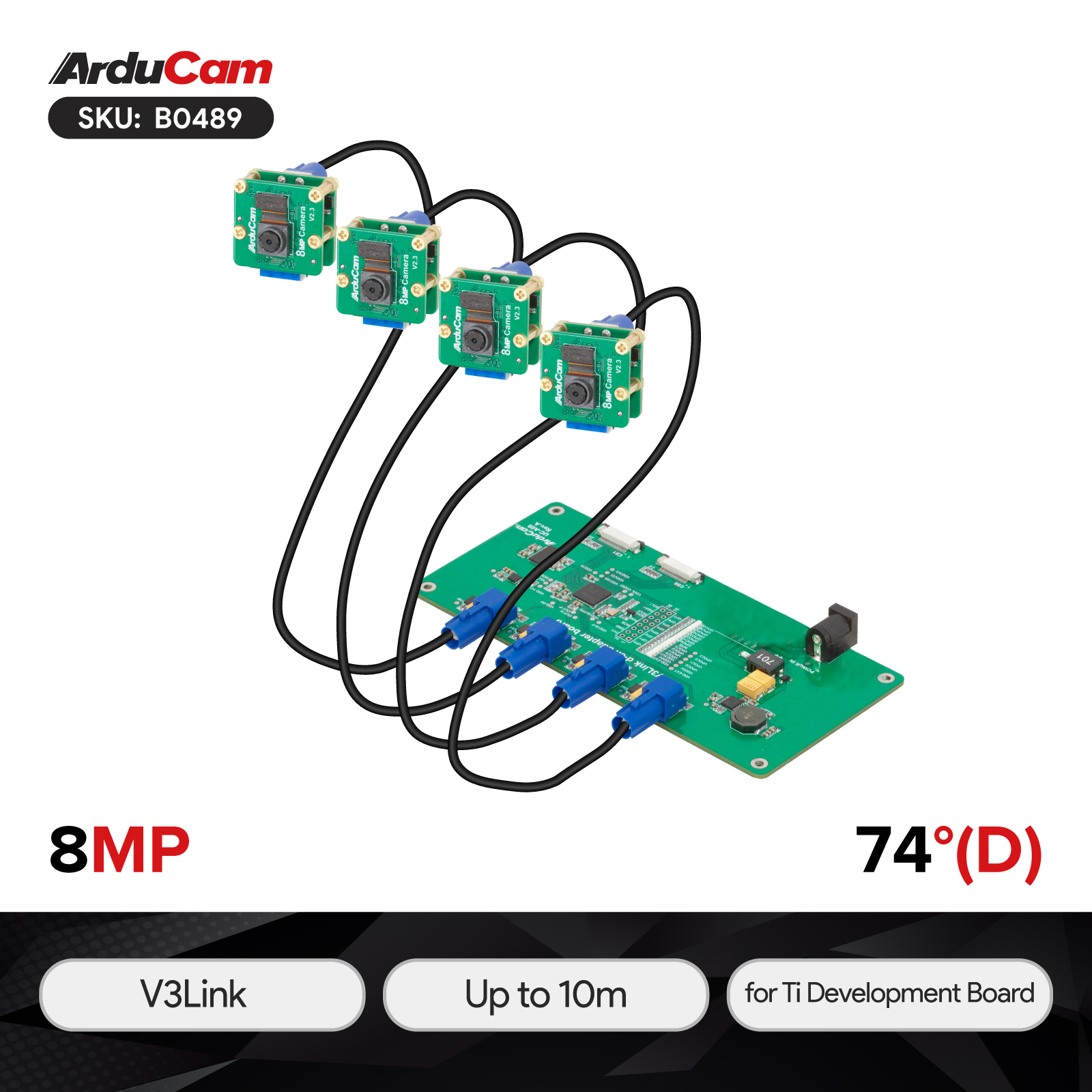 |
B0489 | 8MP | IMX219 | FPD Link Coax Cable | 0-10m | Fixed Focus | 62.2°(H)×48.8°(V) | Integral IR-cut Filter | 300mA |
Pin Definition & Connector
TX Serializer
Input MIPI Connector: F32R-1A7H1-11022
Output FAKRA Connector: 73403-5072
Serializer Pin Definition:
| Pin No. | PIN NAME | TYPE | DESCRIPTION | Level |
|---|---|---|---|---|
| 1 | DGND | Ground | Power ground | GND |
| 2 | MDN0 | Input | Pixel Data Lane0 Negative | 1.2V |
| 3 | MDP0 | Input | Pixel Data Lane0 Positive | 1.2V |
| 4 | DGND | Ground | Power ground | GND |
| 5 | MDN1 | Input | Pixel Data Lane1 Negative | 1.2V |
| 6 | MDP1 | Input | Pixel Data Lane1Positive | 1.2V |
| 7 | DGND | Ground | Power ground | GND |
| 8 | MCN | Input | Pixel Clock Output Form Sensor Negative | 1.2V |
| 9 | MCP | Input | Pixel Clock Output Form Sensor Positive | 1.2V |
| 10 | DGND | Ground | Power ground | GND |
| 11 | MDN2 | Input | Pixel Data Lane2 Negative | 1.2V |
| 12 | MDP2 | Input | Pixel Data Lane2 Positive | 1.2V |
| 13 | DGND | Ground | Power ground | GND |
| 14 | MDN3 | Input | Pixel Data Lane3 Negative | 1.2V |
| 15 | MDP3 | Input | Pixel Data Lane3 Positive | 1.2V |
| 16 | DGND | Ground | Power ground | GND |
| 17 | POWER-EN | Output | Power Enable | 3.3V |
| 18 | LED-EN | Output | Led Enable/XCLK | 3.3V |
| 19 | DGND | Ground | Power ground | GND |
| 20 | SCL | Output | SCCB serial interface clock output | 3.3V |
| 21 | SDA | I/O | SCCB serial interface data I/O | 3.3V |
| 22 | VCC | Power | 3.3V Power supply | POWER |
RX Deserializer
Input FAKRA Connector: 73403-5112
Output MIPI Connector: F32R-1A7H1-11022
Deserializer Pin Definition:
| Pin No. | PIN NAME | TYPE | DESCRIPTION | Level |
|---|---|---|---|---|
| 1 | DGND | Ground | Power ground | GND |
| 2 | MDN0 | Input | Pixel Data Lane0 Negative | 1.2V |
| 3 | MDP0 | Input | Pixel Data Lane0 Positive | 1.2V |
| 4 | DGND | Ground | Power ground | GND |
| 5 | MDN1 | Input | Pixel Data Lane1 Negative | 1.2V |
| 6 | MDP1 | Input | Pixel Data Lane1Positive | 1.2V |
| 7 | DGND | Ground | Power ground | GND |
| 8 | MCN | Input | Pixel Clock Output Form Sensor Negative | 1.2V |
| 9 | MCP | Input | Pixel Clock Output Form Sensor Positive | 1.2V |
| 10 | DGND | Ground | Power ground | GND |
| 11 | MDN2 | Input | Pixel Data Lane2 Negative | 1.2V |
| 12 | MDP2 | Input | Pixel Data Lane2 Positive | 1.2V |
| 13 | DGND | Ground | Power ground | GND |
| 14 | MDN3 | Input | Pixel Data Lane3 Negative | 1.2V |
| 15 | MDP3 | Input | Pixel Data Lane3 Positive | 1.2V |
| 16 | DGND | Ground | Power ground | GND |
| 17 | POWER-EN | Output | Power Enable | 3.3V |
| 18 | LED-EN | Output | Led Enable/XCLK | 3.3V |
| 19 | DGND | Ground | Power ground | GND |
| 20 | SCL | Output | SCCB serial interface clock output | 3.3V |
| 21 | SDA | I/O | SCCB serial interface data I/O | 3.3V |
| 22 | VCC | Power | 3.3V Power supply | POWER |
Related Docs
Quick Start Guide for TI Development Board