OG02B10 MIPI Camera with USB3.0 Camera Shield Plus
1.Introduction
Arducam USB3 camera Shield board is the latest super high-speed USB camera expansion board, which provides improved performance and enhanced functions than the previous USB2.0 camera expansion board. It not only supports high resolution and high frame rate image sensors but also supports stereo camera and IRCUT control functions. Using a given camera profile, users can switch between different cameras effortlessly. It is an ideal solution for camera evaluation/testing, robots/drones, the Internet of Things, machine vision, and scientific applications. Now it supports embedded systems such as PC and Raspberry Pi well, and can also provide customized support TK/TX boards for Odroid, Beaglebone Black, and Nvidia JETSON. Now we will introduce you to how to use Arducam’s Shield development kit to evaluate OG02B10. Please also note that the performance will be greatly reduced (the maximum transmission bandwidth is reduced from 360MB to 40MB) when this USB3 camera is used in the USB2 port (modified the configuration file).
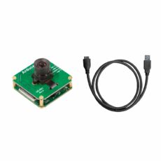
2.Package
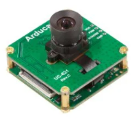
| OG02B10 Camera Board(UC-621 Rev.C) | 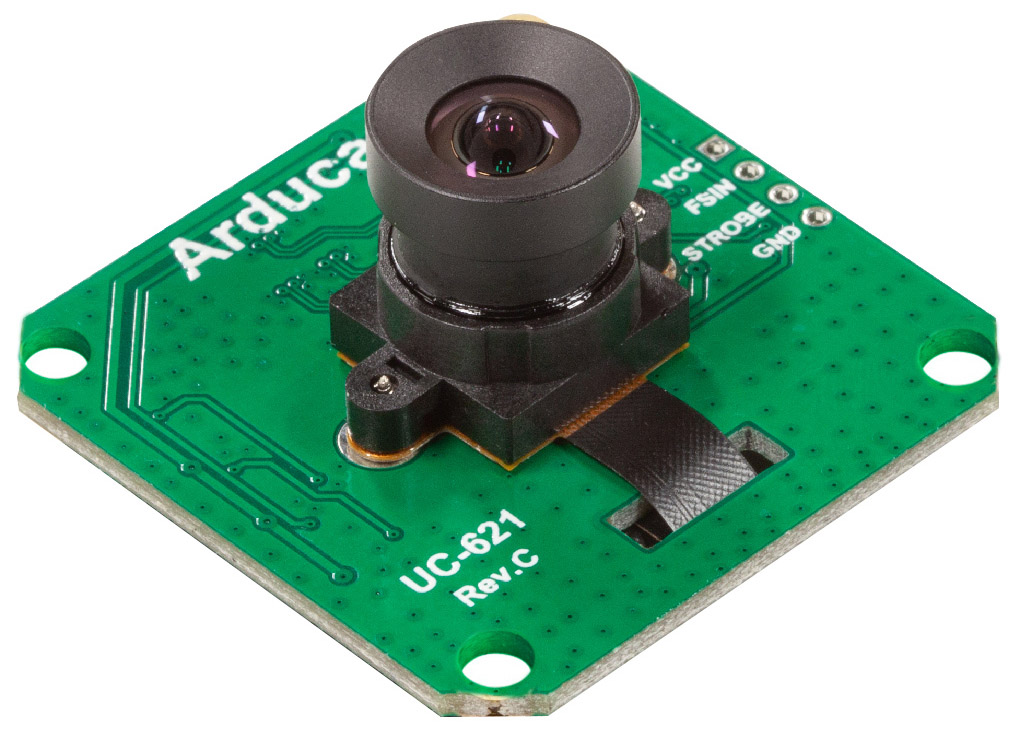 |
|---|---|
| USB3.0 Camera Shield Plus(UC-593 Rev.C) | 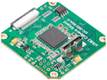 |
| 22pin,0.5mm,Different side,8cm | 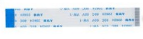 |
| Micro USB3.0 | 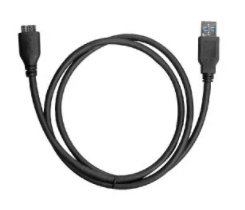 |
3.Hardware
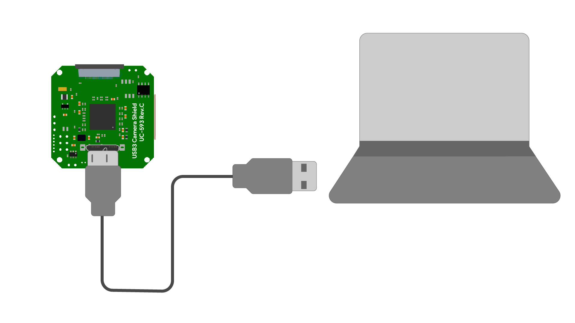
Usually, the delivery status same as the following figure. One end of the FPC cable is connected to the camera board, and the other end is connected to the shield MIPI A. You only need to use a Micro usb3.0 cable to connect the hamburger to your PC.

Connect the hamburger to your PC
4.Software
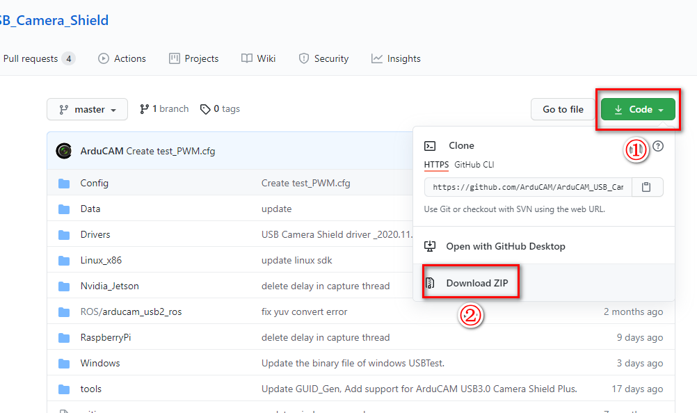
4.1 Download and extract the Toolkit
Click here to go to Arducam GitHub.
4.2 Driver Installation
- Plug the USB cable into the camera and the host PC USB port
- Go to Start -> Settings -> Control-Panel -> Device Manager, right-click the unknown device, and select “Update Driver Software”
- Right-click This PC and then click Manage to find the Device Manager under System Tools on Windows 10
- Select the “Browse my computer for driver software”
- Select “Let me pick from a list of device drivers on my computer”
- Select “Show All Devices”
- Press the “Have Disk” button
- Enter the path to the ArduCAM USB2 driver, where you save the downloaded file in ArduCAM_USB_Camera_Shield-master\Drivers
- Confirm the installation of the driver by pressing “Yes”
- Confirm the installation again by pressing “Install”
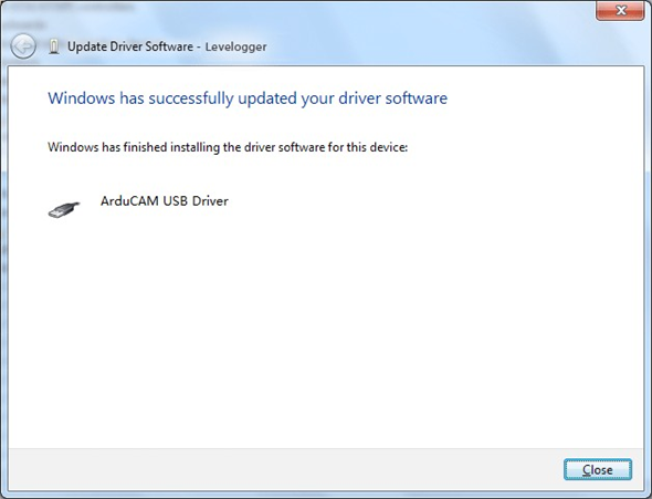
- You will successfully install the driver like this
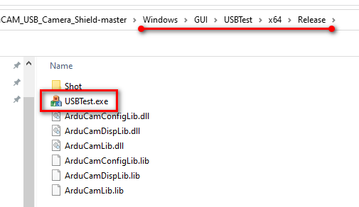
4.3 Run USBTest.exe
Run the USBTest.exe in \Windows\GUI\USBTest\x64*Release*
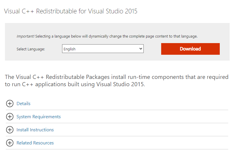
Note
If you are prompted that the library such as “MFC140.dll” is missing, you need to install the Microsoft Visual C++ 2015 Redistributable Package.
https://www.microsoft.com/en-us/download/details.aspx?id=48145
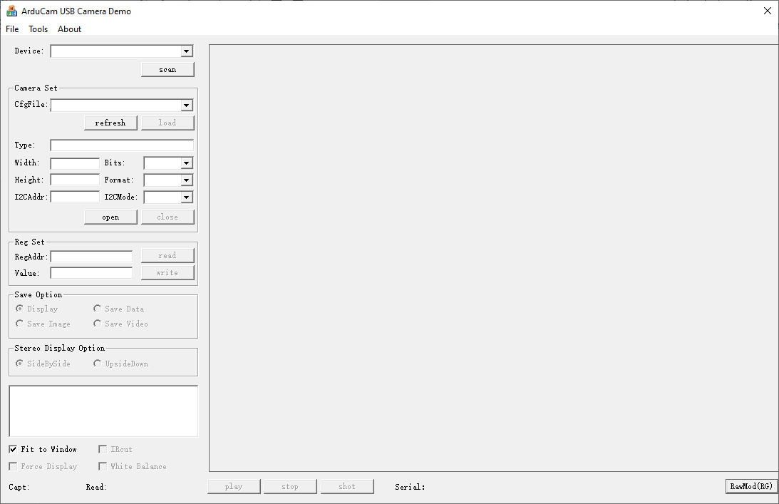
4.4 USBTest.exe instructions
4.1.1 Preview the image
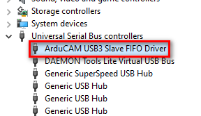
- Check the device
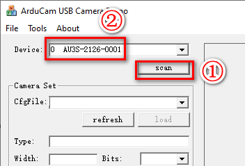
- Scan the device on USBTest.exe
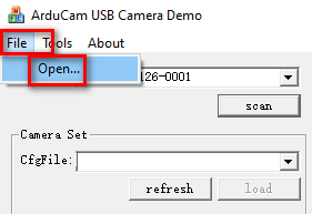
- File->Open
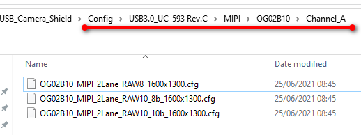
- Select the Configuration file in ArduCAM_USB_Camera_Shield\Config\USB3.0_UC-593 Rev.C\MIPI*OG02B10*\Channel_A
Note
There are multiple combinations of the USB Camera Shield series, which correspond to different configuration folders. You cannot choose the wrong one, otherwise it will affect the output of the picture.
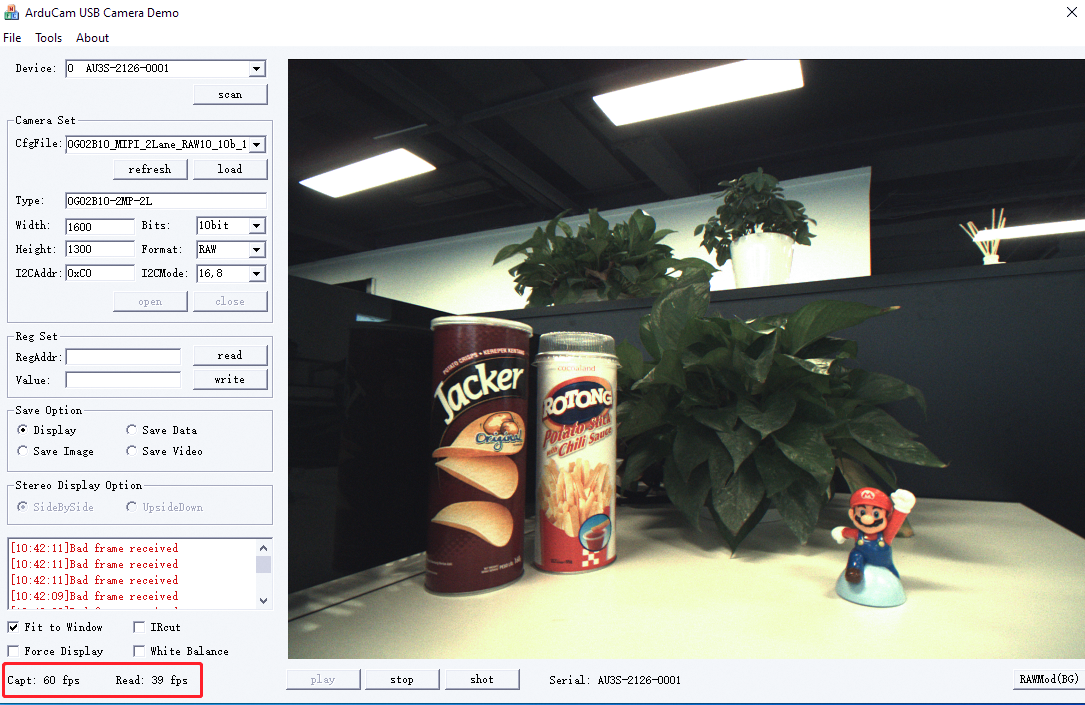
- Load->Open->Play

- The frame will be displayed.
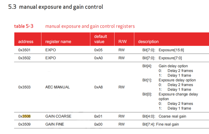
4.1.2 Adjust frame rate & exposure & gain
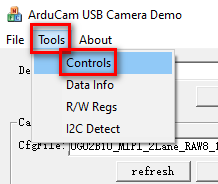
- Tools->Controls
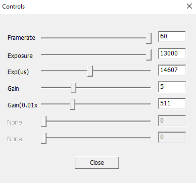
Note
If the exposure is stretched to a certain value, it will not work, it may be that the exposure value exceeds the VTS. At this time, reduce the number of frames (stretch the VTS), and the exposure should continue to take effect.
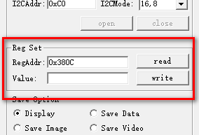
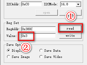
4.1.3 Read and Write the registers
You can read and write camera registers and modify the camera status online to facilitate testing.
- Single register can be read and written
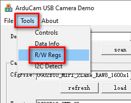
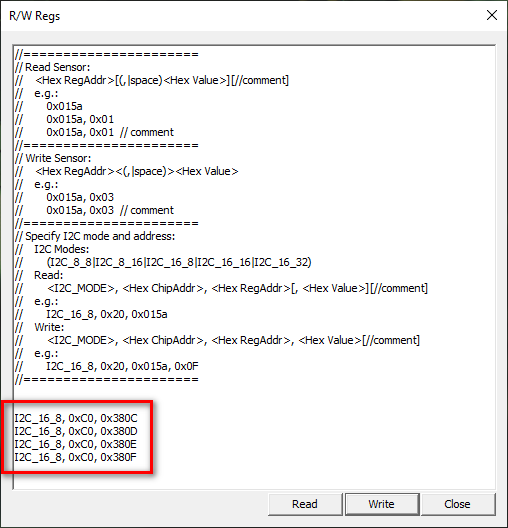
- Tools->R/W Regs(Batch read and write)
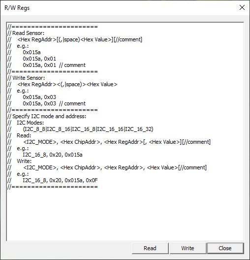
Example
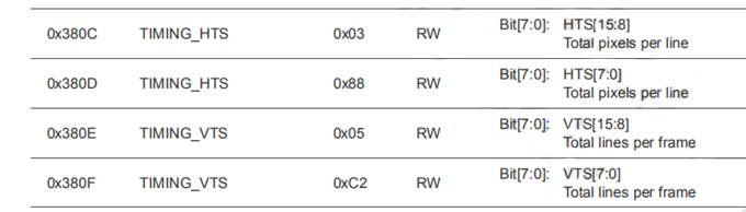
Copy the following statement to the R/W Regs window
I2C_16_8, 0xC0, 0x380C
I2C_16_8, 0xC0, 0x380D
I2C_16_8, 0xC0, 0x380E
I2C_16_8, 0xC0, 0x380F
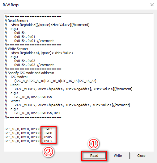
 Read
Read
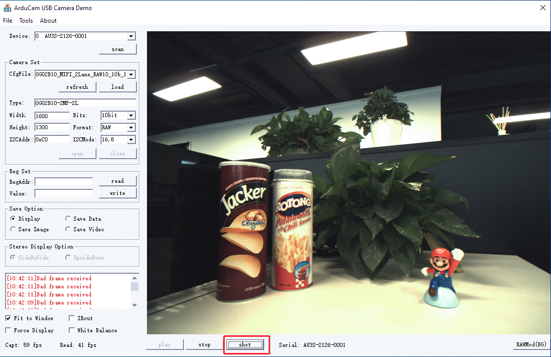
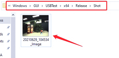
4.1.4 Capture and save image
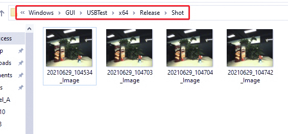
- Press shot capture an image and save as bmp format in Release\shot.
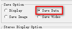
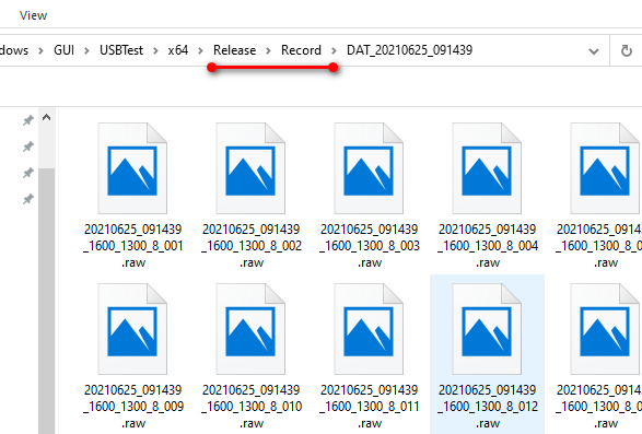
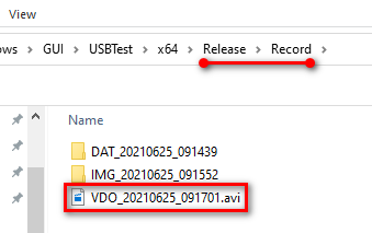
- Select Save data to continuous save images as raw format in Release\Record.
Note
Saving images for a long time will take up a lot of memory space.
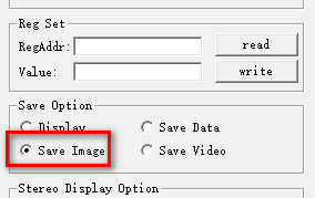
- Select Save Image to continuous save images as bmp format
4.1.5 Capture and save video
- Select Save Video to capture video and save as AVI format
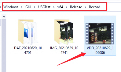
Note
Saving video for a long time will take up a lot of memory space.
4.1.6 Modify the Configuration file
If some camera register values in the configuration file are not suitable, you can open the configuration file with a text editor to modify it. The following is the camera’s register. Refer to the existing format to modify the register value or add a register.
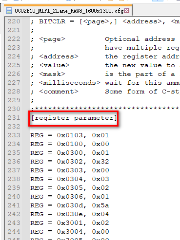
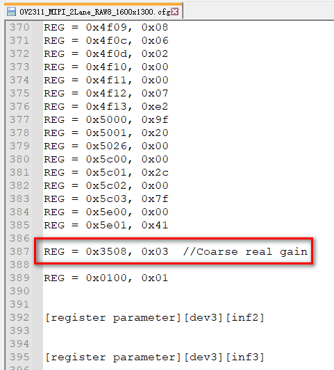
Note
Some camera registers may not support online modification and need to be written in the configuration file to take effect.