Hardware Trigger with External Signal
This article is a tutorial on a multi-camera synchronizing application with the Arducam USB camera shield. We will connect and synchronize three OV9281 global shutter MIPI camera modules with our USB3.0 Camera shield and an Arduino board as the external trigger.
What’s used
- 3× Arducam OV9281 global shutter MIPI camera module
- 3× Arducam USB3.0 Camera Shield
- 3× MIPI Camera Adapter for Arducam USB3.0 Camera Shield
- 3× USB3.0 cable for Arducam USB3.0 Camera Shield
- 1× Arduino UNO R3
- 1× Windows PC
- 1× USB Cable for connecting the Arduino to PC
- Breadboard and jumper wires
Before we start
We need to dig into the feasibility with some math before we start this tutorial. An OV9281 camera module running full resolution at 120fps will require a bandwidth of 983Mbps (1280×800×120×8), while three of them working simultaneously requires even higher bandwidth at 2.88Gbps (983×3÷1024). The USB3.0 port on your computer might not be able to reach this ceiling, leading to decreased performances.
Hardware connection
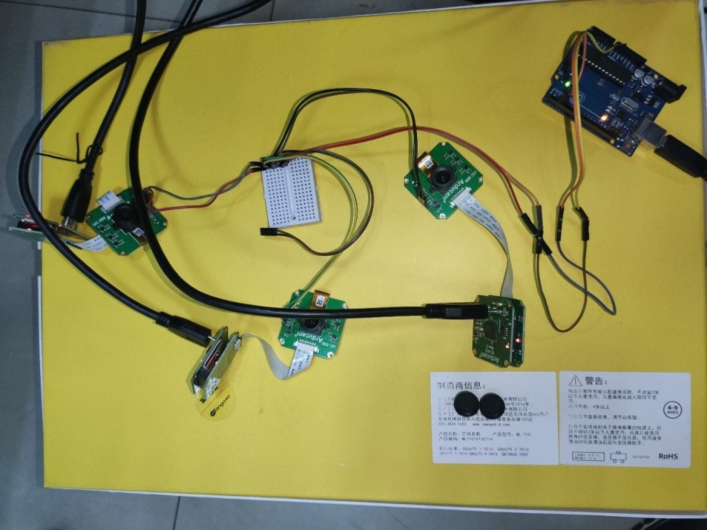
1.Camera Connection
Connect the OV9281 camera module to the MIPI adapter board, and the adapter board on the Arducam USB3.0 Camera shield. Use the USB3.0 cable to connect the shield to the USB3.0 port on your Windows PC.
2.Hardware Trigger connection
The FSIN pin of the OV9281 camera is used to trigger the signal input. In this example, the 2pin of the Arduino UNO is connected to the FSIN pin of the OV9281, and its GND to the GND of the OV9281. Pulse width 100us, level 3.3v, 8ms interval between each trigger.
Run the demo
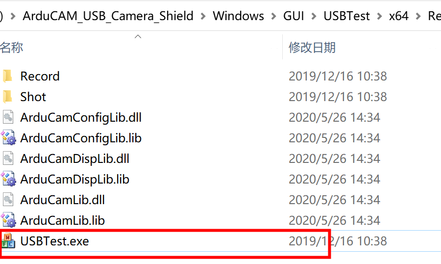
1.Running three USBTest instances
The Windows GUI program for the Arducam USB camera shield is USBTest.exe. Since the program shows one camera feed each window, you will be opening multiple instances of this program for multi-camera applications with the USB camera shield.
2. Scan and select the camera with different device number
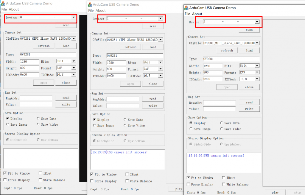
Hit scan in each window, and in the drop-down menu of device, select a different device for each instance.
3. Select the configuration file
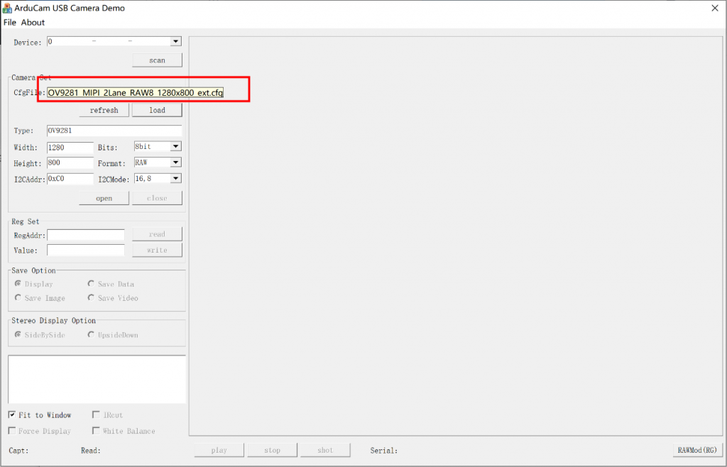
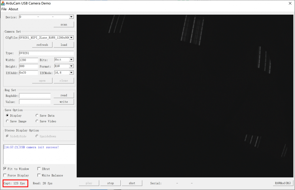
In the drop-down menu of CfgFile, select the one named OV9281_MIPI_2Lane_RAW8_1280x800_ext.cfg. Please note that the exposure of this configuration is set to a relatively low level.
4. Click openthe enable the camera
5. Click play to receive the feed.
6. Send external signals with the hardware trigger.
This tutorial uses an Arduino UNO R3 board as the triggering source. Please see the demo code below.
byte led = 2;

void setup() {
  pinMode(led, OUTPUT);
}

void loop() {
  digitalWrite(led, HIGH);
  delayMicroseconds(100);
  digitalWrite(led, LOW);
  delay(8);
}
7. Check the rate of receiving images
The real-time frame rate of image capturing is displayed at the lower bottom of the window.