Quick start
Automatic IR-Cut filter control
The majority of switchable IR-cut filters are deployed for surveillance use, which requires the camera to maintain color accuracy throughout the daytime and night vision at night.
We don’t have to tell whether it’s already nighttime, because a light-sensitive trigger would do the work. A photoresistor is such a trigger, and it can determine whether the lighting condition is poor, so the IR illumination should be turned on and the IR filter switched off.
Arducam day-night vision cameras use photoresistors to automate the IR switching. This is the default option and no extra settings are required.
Manual IR-Cut filter control workaround
Although automatic IR-cut filter control can satisfy most users, some may still want a more proactive method to control it manually. Some workarounds are needed for this.
Working like a normal camera: Keep the IR filter always on
The black and red wires will lead you to a connector of the IR cut-off filter to the camera board. Unplugging the connector will disable the IR filter switch and make it a normal camera.
Working like a NoIR camera: Keep the IR filter always off
Photoresistors rely on lighting conditions to work. If you cover the photoresistor with a non-translucent material, it will produce the same result as a NoIR camera.
Manually control the IR-filter with scripts
Install the driver and libcamera
Find your corresponding camera in the following two links, and then execute the following command
Note
If you do not find your camera please contact us.(support@arducam.com)
For the Raspberry Pi 4
Originally, the camera LED pin was used to control the IR cut filter. However, the Pi 4 has had the camera LED GPIO line removed as it is not used on the V2.1 camera module. So the steps on Pi 4 would be different from the previous models.
1. Remove the photoresistor.
If you want the photoresistor to quit controlling and your scripts to take over, remove the photoresistor first.
2. Connect the Camera IR and GND pins to the RPI GPIO
Do it as shown in the image below. You may need some soldering and jumper wires.
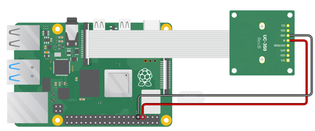 Connect the camera IR and GND pins to RPI GPIO
3. Download the code
git clone https://github.com/ArduCAM/RPI_Motorized_IRCut_Control.git
4. Update the wiringPi library
cd /tmp
wget https://project-downloads.drogon.net/wiringpi-latest.deb
sudo dpkg -i wiringpi-latest.deb
5. Control the IR-cut filter with commands
Enter the folder:
cd RPI_Motorized_IRCut_Control
Switch the IR-cut filter on:
python RPI_Camera_PI4_Ircut_ctl.py on
Switch off the IR-cut filter:
python RPI_Camera_PI4_Ircut_ctl.py off
For the Raspberry Pi 3B+ and previous models
For these models, we use the camera LED pin to control the IR cut filter.
1. Remove the photoresistor and weld a 470 ohm resistor
Do it as shown in the images below. Click on the image to enlarge.
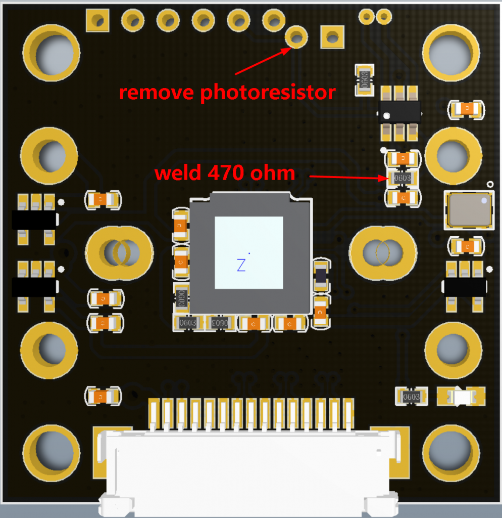
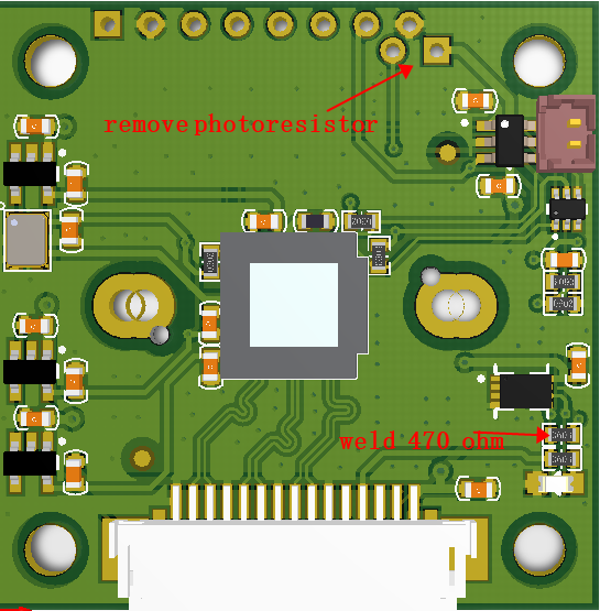
5MP OV5647 Camera Board 8MP IMX219 Camera Board
2. Download the code
git clone https://github.com/ArduCAM/RPI_Motorized_IRCut_Control.git
3. Compile source code
Enter the folder:
cd RPI_Motorized_IRCut_Control/camIrCutControl/
Compile source code:
make
4. Control the IR-cut filter with commands
Switch the IR-cut filter on:
./irCut 1
Switch off the IR-cut filter:
./irCut 0