Access Global Shutter Camera using external trigger snapshot mode
Introduction
Global Shutter Camera having an external trigger function, which is used to capture the image and helps in synchronized streaming by connecting two or multiple cameras. In production applications (such as assembly line production), the external trigger mode can easily synchronize the camera with other devices. In addition, the sensor enables the sleep state will greatly reduce the power consumption.
Supported Cameras
| Product Image | SKU | Sensor | Resolution | Pin/Connect Type | Color Type | Features | Lens Type | Field of View(HxV) | Focus Type | IR Sensitivity |
|---|---|---|---|---|---|---|---|---|---|---|
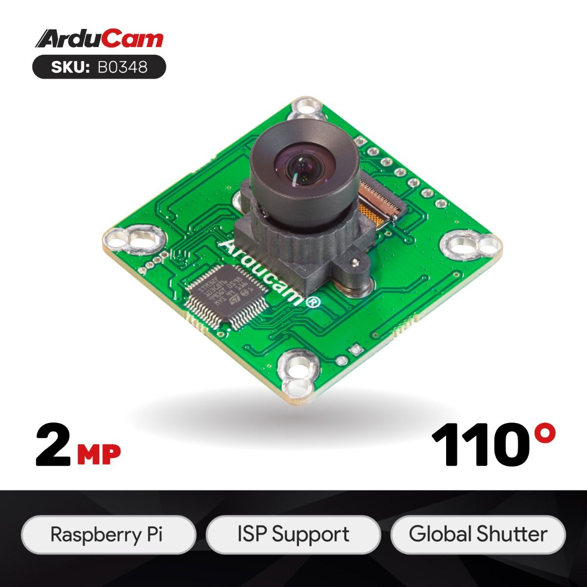 |
B0348 | OG02B10 | 2MP | 22/Top | Color | Pivariety | M12 | 85° (H) x 69° (V) | Manual Focus | 650nm IR-cut filter |
 |
B0353 | AR0234 | 2MP | 22/Top | Color | Pivariety | M12 | 90° (H) x 56° (V) | Manual Focus | without IR-cut filter |
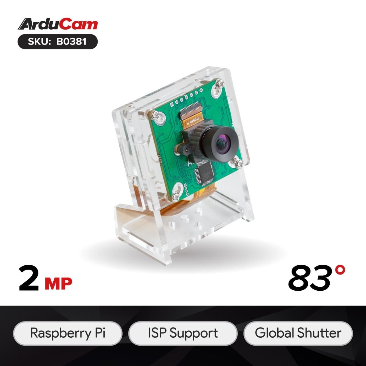 |
B0381 | OV2311 | 2MP | 22/Top | Monochrome | Pivariety | M12 | 83°(H) x 67.5°(V) | Manual Focus | without IR-cut filter |
Hardware
Abstract
The external trigger pins used by different cameras may not be the same. For example, the OV9281 camera mainly uses the XVS pin as the external trigger pin, while other cameras use pins such as FSIN and Trigger. For specific pin information, you can refer to the camera datasheet.
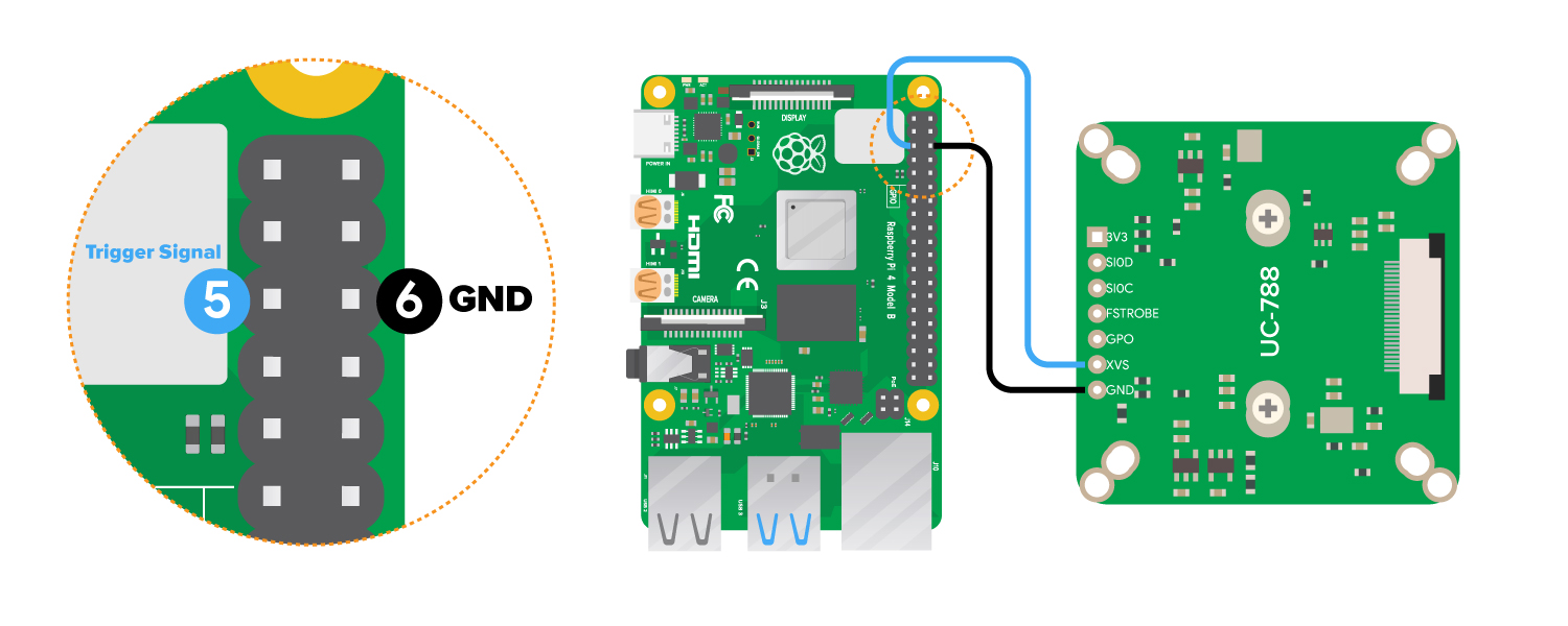
First of all, You need to solder the headers on the TRIGGER/XVS/FSIN and GND pins, TRIGGER/XVS/FSIN is connected to the external trigger signal, and GND is connected to the ground.
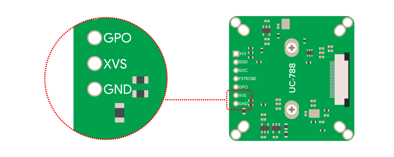
- XVS Pin
We have adapted the new board (UC-788) for some specific cameras such as the new version of OV9281/OG02B10/OV2311 cameras, etc.
Note
It is required that the voltage of the trigger signal is 1.8V, you need to convert the 3.3V or 5V to 1.8V. The trigger signal pulse width tFSIN_High is not less than 2us, and the frequency cannot exceed the highest external trigger frame rate supported by the current frame rate.

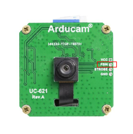
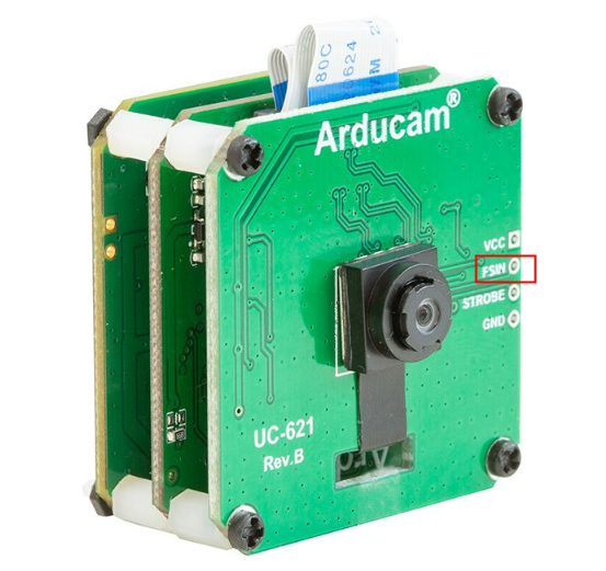
- FSIN Pin
Some of the Arducam cameras adopt FISN pin as the external trigger pin.
 |
 |
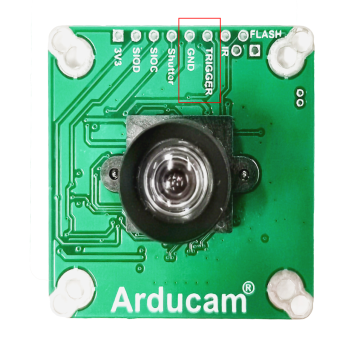
- Trigger Pin
Note
It is required that the voltage of the trigger signal is 1.8V, you need to convert the 3.3V or 5V to 1.8V. The trigger signal pulse width TTPW is not less than 2us, and the frequency cannot exceed the highest external trigger frame rate supported by the current frame rate.

Software
1. Start the camera with libcamera-still command
libcamera-still -t 0 --shutter 1000
Note
We recommend a fixed exposure time to prevent automatic exposure from interfering with the external trigger working properly.
2. Enable the external trigger snapshot mode
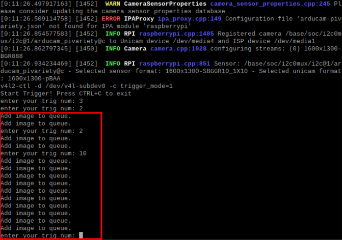
v4l2-ctl -d /dev/v4l-subdev0 -c trigger_mode=1
3. Input the external trigger signal at XVS pin and capture the image
Note
The external trigger mode of the Pivariety OG02B10 Camera Module default setting is auto exposure, you can adjust the exposure time to capture a good image. Refer to the command to adjust the exposure time: libcamera-still -t 0 --shutter 100
4. Download and run the trigger script
wget -O trigger.py https://github.com/ArduCAM/MIPI_Camera/releases/download/trigger_v1.0/trigger.py
python3 trigger.py
Example as XVS Pin:
Please confirm the pin XVS connected to the RPI’s Trigger Signal.

5. Disable the external trigger signal snapshot mode
v4l2-ctl -d /dev/v4l-subdev0 -c trigger_mode=0
External trigger example
Abstract
To enhance your interest and understanding of external triggering functionality, we have provided the following examples.
Download the example code
You can find the example code here: –code
Note
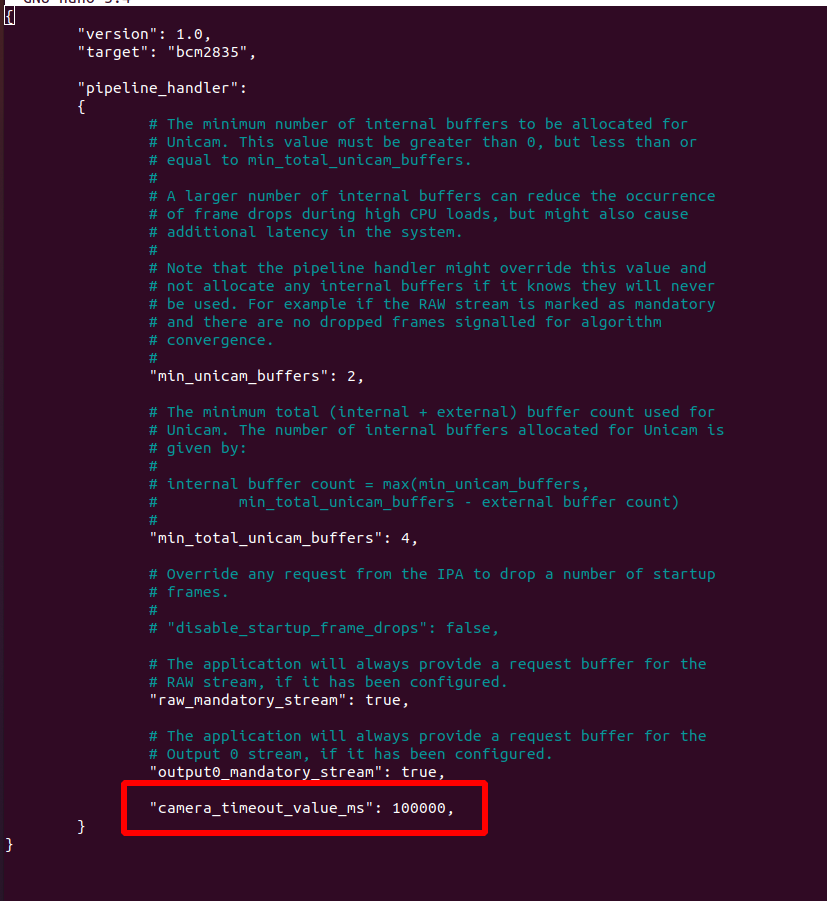
How to set the timeout value:
You can set the camera timeout by modifying the rpi_apps.yaml file:

Add the camera_timeout_value_ms parameter in the last line of the file:
How to use
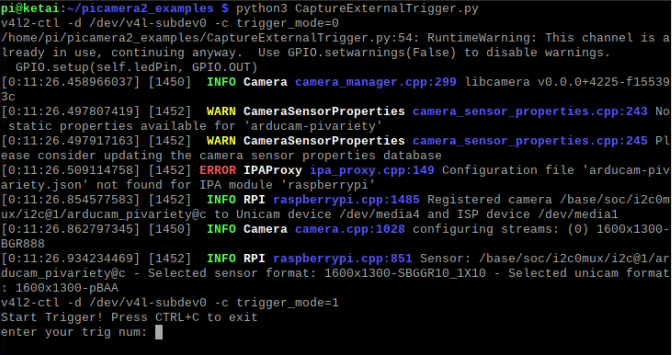
Open your termimal, and run the commands below.
1.export LIBCAMERA_SET_TIMEOUT=1000000 # (1)!
2.git clone https://github.com/ArduCAM/picamera2_examples.git
3.cd picamera2_examples
4.python3 CaptureExternalTrigger.py
- In order for the timeout setting to take effect, you must run the example in the same terminal session.
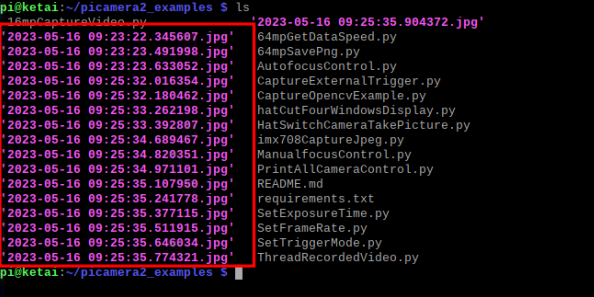
The first three frames need to be filtered out:
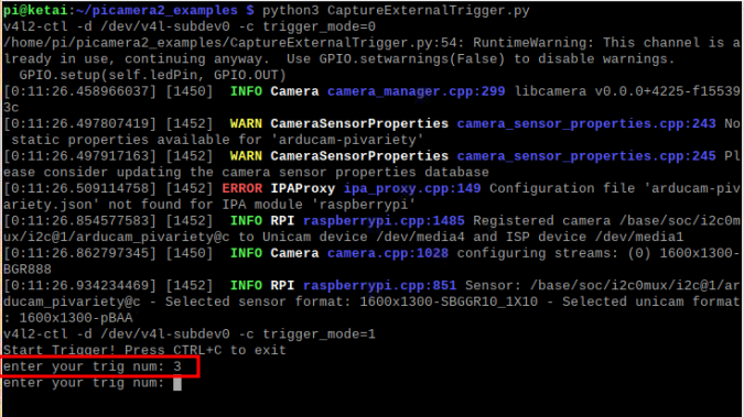
From now on, every time a device triggers a signal, it will be saved as a file named 'time.jpg'. If you see the message 'Add image to queue', it means the image has been successfully saved.
The image will be saved with a name following the format shown in the example below: