Arducam MIPI Adapter Board for USB3.0 Camera Shield
Introduction
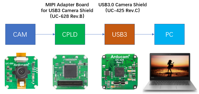
Arducam MIPI Adapter Board for USB3 Camera Shield (UC-628 Rev. B) works with Arducam USB3.0 Camera Shield (UC-425 Rev. C) to enable the USB3.0 platform to receive MIPI camera data.
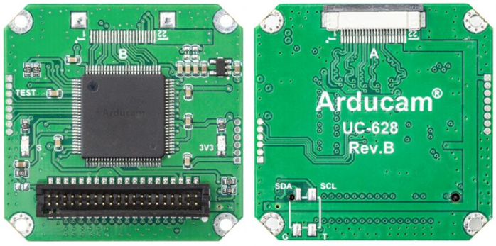
Arducam MIPI Adapter Board for USB3.0 Camera Shield(UC-628 Rev.B)
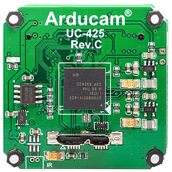 Arducam USB3.0 Camera Shield(UC-425 Rev.C)
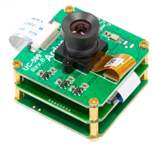
For example, you can connect OV9281 camera to MIPI adapter board and USB3.0 camera shield. Then you will get the following product:
Arducam MIPI Adapter Board for USB3.0 Camera Shield (UC-628 Rev. B) and Arducam USB3.0 Camera Shield (UC-425 Rev. C) can be used with different cameras or different modes of the same camera. The upper computer needs to load different configuration files.
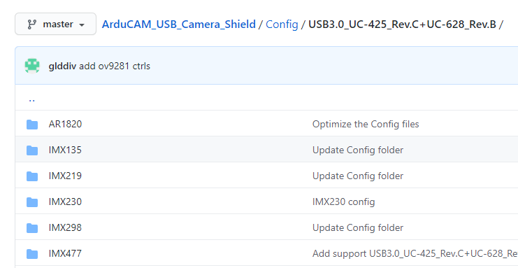
Arducam MIPI Adapter Board for USB3.0 Camera Shield (UC-628 Rev.B) configuration files:
https://github.com/ArduCAM/ArduCAM_USB_Camera_Shield/tree/master/Config/USB3.0_UC-425_Rev.C%2BUC-628_Rev.B
Configuration Files Guide
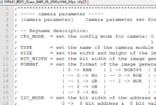
The following configuration file will be used as an example to illustrate a detailed description of the contents of the configuration file, so that you can modify it to suit your needs.
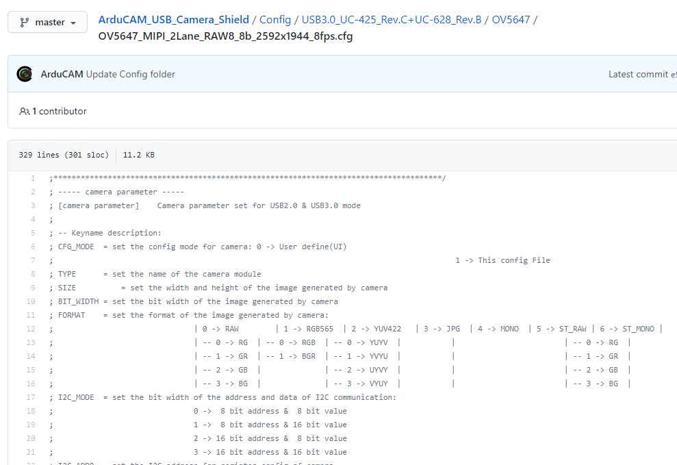
About Comments
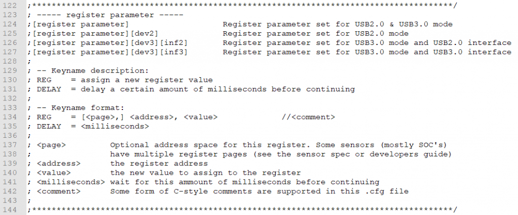
The lines starting with “;” and “//” are all comments.
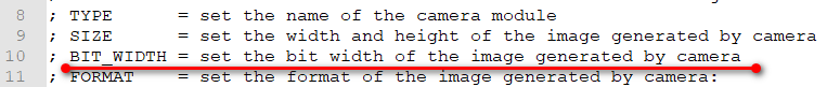
Large comments at the beginning of the configuration file are a description of the display mode, camera address, and other configuration methods.
Comments are sometimes added after the camera register configuration to explain the register function.
Display Mode and Camera Address Configuration
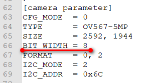
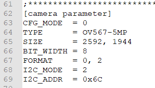
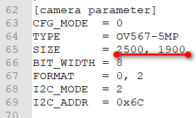
Lines starting with [camera parameter] are for configuring the display mode and camera address.
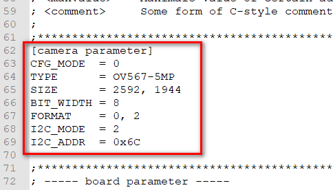
① CFG_MODE
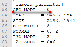

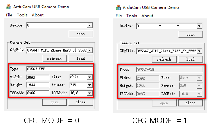
CFG_MODE = 0:Parameters can be modified in the upper computer software interface.
CFG_MODE = 1:Parameters can not be modified in the upper computer software interface.
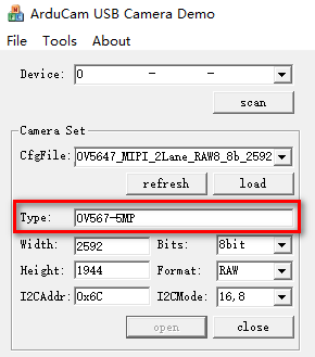
② TYPE
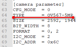

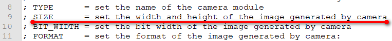
TYPE is used to mark the camera model for easy viewing.
Note
TYPE is just a comment, it doesn’t matter if you write it wrong.
③ SIZE
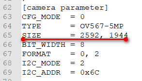
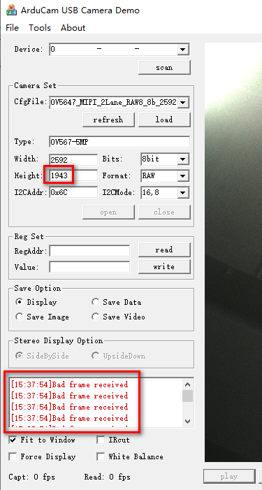
If it does not match the actual output resolution of the camera, a Bad frame received error will be displayed.
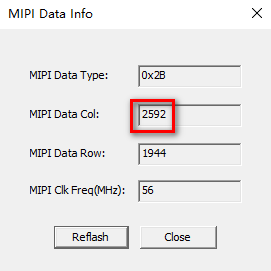
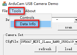
Click 【Tools】-【Data Info】 to view the MIPI camera resolution message from the hardware CPLD in real time.
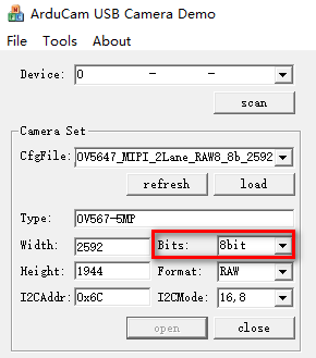
④ BIT_WIDTH
NOTE:
- MIPI RAW8 mode: camera output is 8bit, BIT_WIDTH is set to 8bit.
- MIPI RAW10 mode: camera output is 10bit. Because the upper computer cannot parse RAW10 at the moment, the CPLD hardware is throwing away the lower two bits of 10bit and turning them into 8bit before uploading, so BIT_WIDTH is also set to 8bit.
- *MIPI RAW1*2 mode: DVP input is 12bit. Because the upper computer cannot parse RAW12 at the moment, the CPLD hardware is throwing away the lower four bits of 12bit and turning them into 8bit before uploading, so BIT_WIDTH is also set to 8bit.
④ FORMAT
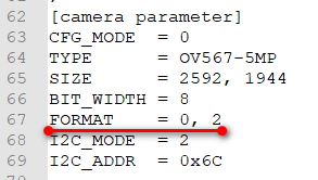
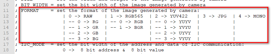
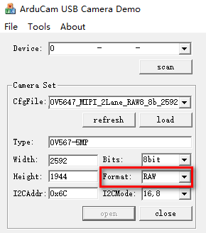
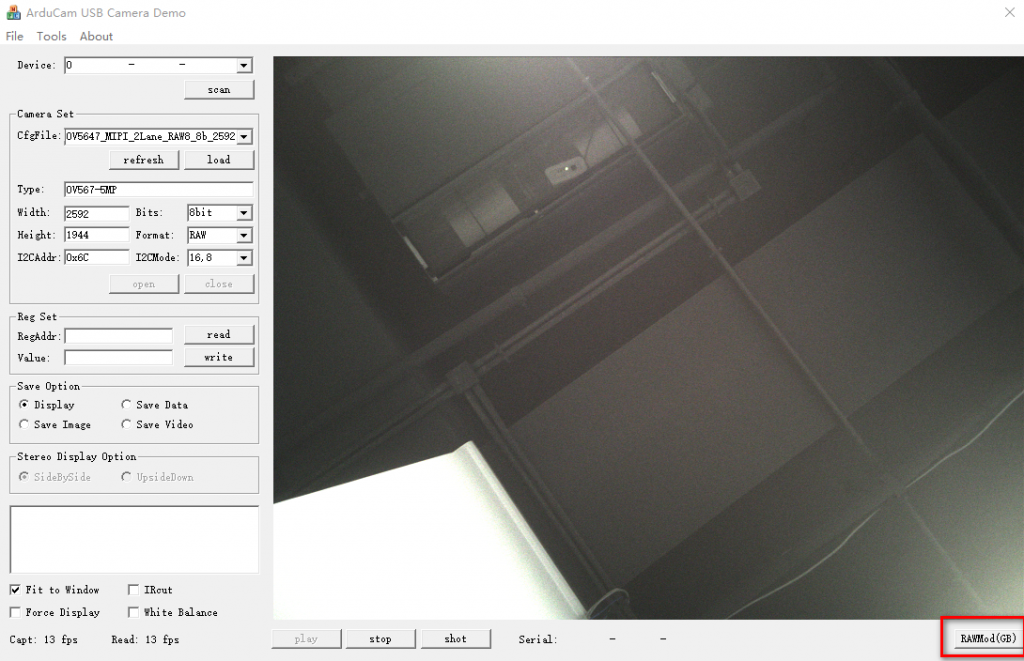
FORMAT = 0, 2 means the order of GB in the four arrangements of RAW, or you can load the configuration file and then switch to adjust it in the lower right corner of the upper computer.
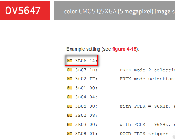
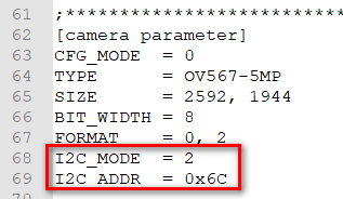
⑤ I2C_MODE & I2C_ADDR
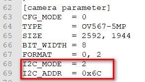
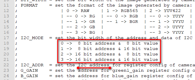
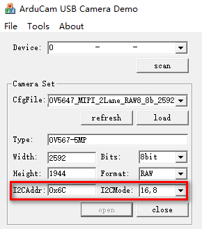
I2C_MODE = 2 means the camera I2C operating mode is 16-bit address, 8-bit data. I2C_ADDR = 0x6C means that the imager device address is 0x6C.
The I2C operating mode and device address of the imager should be referred to the imager manual or other reference materials.

USB Firmware and CPLD Configuration
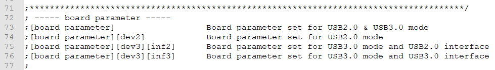
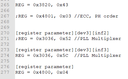
[register parameter]: Register parameter set for USB2.0 & USB 3.0 mode. [register parameter][dev2]: Register parameter set for USB2.0 mode. [register parameter][dev3][inf2]: Register parameter set for USB3.0 mode and USB 2.0 interface. [register parameter][dev3][inf3]: Register parameter set for USB3.0 mode and USB 3.0 interface.
When the USB3.0 Camera Shield is plugged into the USB3.0 port, the configurations in [register parameter] and [register parameter][dev3][inf3] will both work, and the later configurations will overwrite the earlier ones according to the order in which they are written and loaded.
USB Firmware Configuration
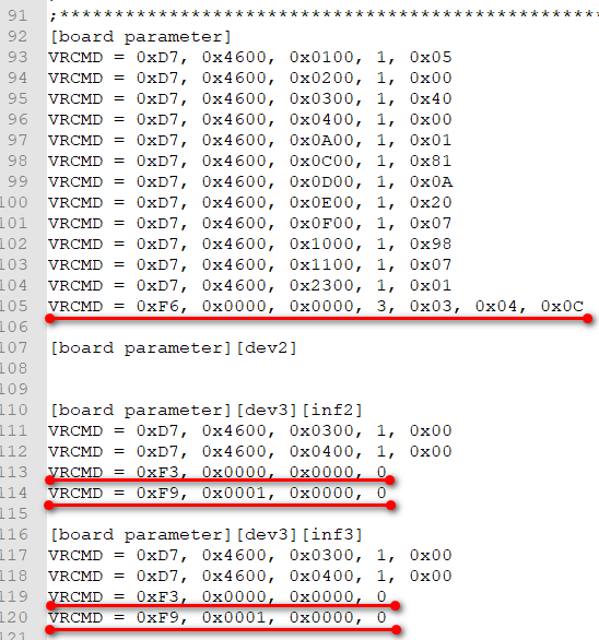
VRCMD = 0xF6, 0x0000, 0x0000, 3, 0x03, 0x04, 0x0C VRCMD = 0xF3, 0x0000, 0x0000, 0 VRCMD = 0xF9, 0x0001, 0x0000, 0 // 0x0001 is 16 bits; 0x0004 is 32 bits
These lines USB3.0 firmware configurations, which generally do not need to be changed.
CPLD Configuration
On the Arducam MIPI Adapter Board for USB3.0 Camera Shield (UC-628 Rev.B) has a CPLD for camera data processing.
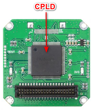
The CPLD can achieve different functions through register configuration.
CPLD is 8-bit address, 8-bit data working mode.
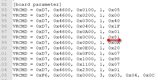
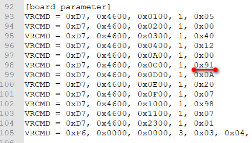
① Set MIPI Lane channel and RAW format
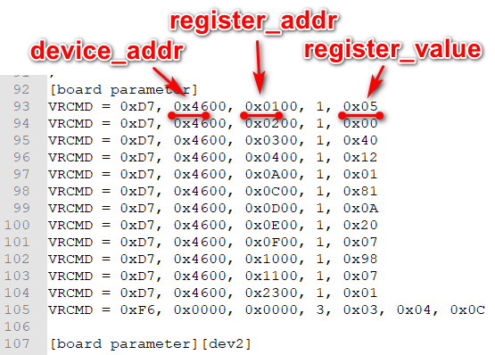
VRCMD = 0xD7, 0x4600, 0x0C00, 1, 0x81
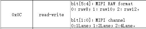
- MIPI Lane channels have 1Lane, 2Lane and 4Lane configurations.
- RAW has three types of RAW8 RAW10 and RAW12 (other RAW formats are not supported at this time).
| Lane channel | RAW Format | 0x0C value |
|---|---|---|
| 1 | RAW8 | 0x80 |
| 2 | RAW8 | 0x81 |
| 4 | RAW8 | 0x82 |
| 1 | RAW10 | 0x90 |
| 2 | RAW10 | 0x91 |
| 4 | RAW10 | 0x92 |
| 1 | RAW12 | 0xA0 |
| 2 | RAW12 | 0xA1 |
| 4 | RAW12 | 0xA2 |
Note
If Lane channel and RAW format are not configured correctly, it will result in the CPLD not being able to parse the MIPI data and the upper computer not being able to output the image.
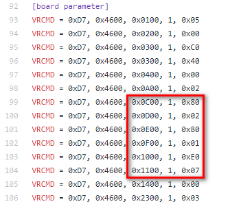
② Set the MIPI resolution reference value
VRCMD = 0xD7, 0x4600, 0x0D00, 1, 0x0A
VRCMD = 0xD7, 0x4600, 0x0E00, 1, 0x20
VRCMD = 0xD7, 0x4600, 0x0F00, 1, 0x07
VRCMD = 0xD7, 0x4600, 0x1000, 1, 0x98
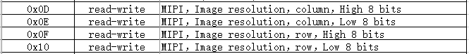
The registers 0x0D to 0x10 are used to set the resolution referenced value. 0x0D to 0x10 is meaningful when the wordcount checksum (bit[2] of register 0x11) is turned on for MIPI resolution.
- If 0x11 is set to 0x03, the wordcount checksum is not turned on, 0x0D ~ 0x10 can be ignored.
- If 0x11 is set to 0x07, 0x0D ~ 0x0E value must be correct, otherwise HREF can not be parsed out, the upper computer can not output the image.
③ Set MIPI checksum
VRCMD = 0xD7, 0x4600, 0x1100, 1, 0x07
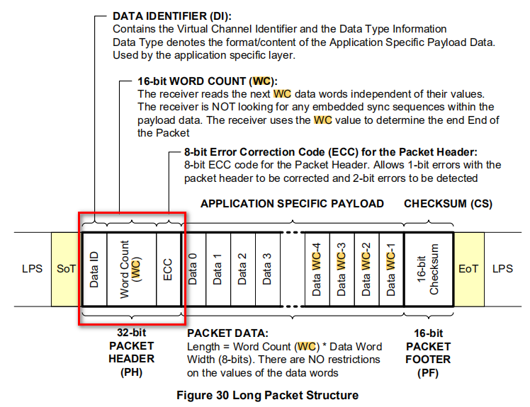
Register 0x11 is used to set several MIPI checksum methods (DataID, WordCount, ECC).
MIPI data contains DataID, WordCount, and ECC data regardless of whether it is a short packet (indicating field start and field end) or a long packet (indicating a line of data).
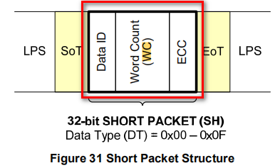
DataID is divided into VC (Virtual Channel) and DT (DataType).
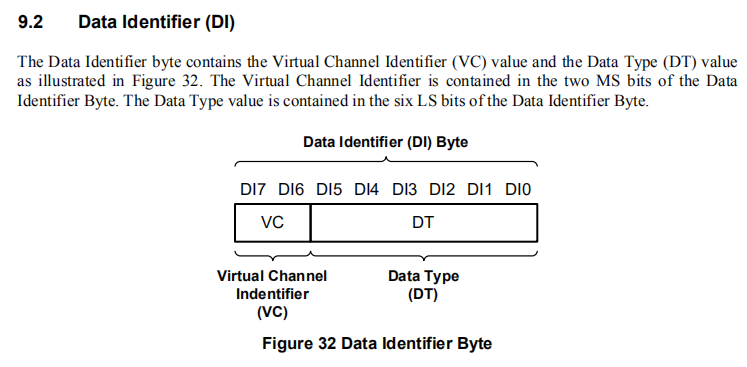
VC is generally not used; RAW8 and RAW10 are commonly used by DT.

Note
If the MIPI checksum is not set or set incorrectly, it may lead to the MIPI data parsing error and can not produce the map.
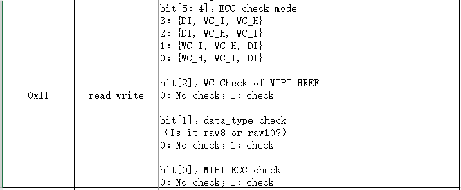
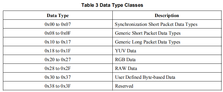
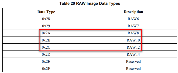
- bit[1] sets the DataType checksum. When set to 1, only MIPI data with RAW8 (DataType=0x2A), RAW10 (DataType=0x2B) and RAW12 (DataType=0x2C) can be parsed.
- bit[2] sets the WordCount check, MIPI data can only be parsed if the WordCount is the same as the set value of 0x0D~0x0E when bit[2] is set to 1.
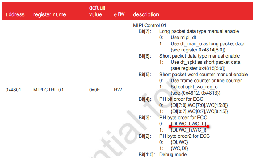
- bit[5:4] sets the order of ECC generation. ECC is generated based on the three bytes DI, WC_H and WC_I, and the ECC values generated by different orders are different.
Most cameras can configure this order, and the default order is usually DI, WC_I, and WC_H.
In general.
- 2Lane or 4Lane only need to enable the ECC check and DataType check, WordCount check could not be enabled. In other words, the 0x11 register is set to 0x03, and it does not matter if the 0x0D to 0x10 registers are not used
VRCMD = 0xD7, 0x4600, 0x1100, 1, 0x03
- WordCount checksum needs to be enabled at 1Lane, otherwise the parsing may be unstable. In other words, 0x11 register is set to 0x07, at this time, 0x0D~0x10 registers need to be set correctly according to the actual resolution, if the resolution is not set correctly, it will cause HREF not to be resolved, and the upper computer will not be able to output the image.
For example, OV7251 1Lane RAW8 configuration:
Camera Configuration
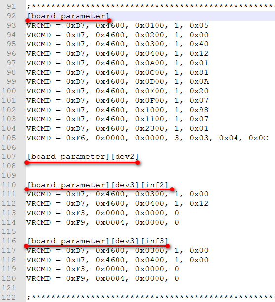
[register parameter]: Register parameter set for USB2.0 & USB 3.0 mode. [register parameter][dev2]: Register parameter set for USB2.0 mode. [register parameter][dev3][inf2]: Register parameter set for USB3.0 mode and USB 2.0 interface. [register parameter][dev3][inf3]: Register parameter set for USB3.0 mode and USB 3.0 interface.
When the USB3.0 Camera Shield is plugged into the USB3.0 port, the configurations in [register parameter] and [register parameter][dev3][inf3] will both work, and the later configurations will overwrite the earlier ones according to the order in which they are written and loaded.
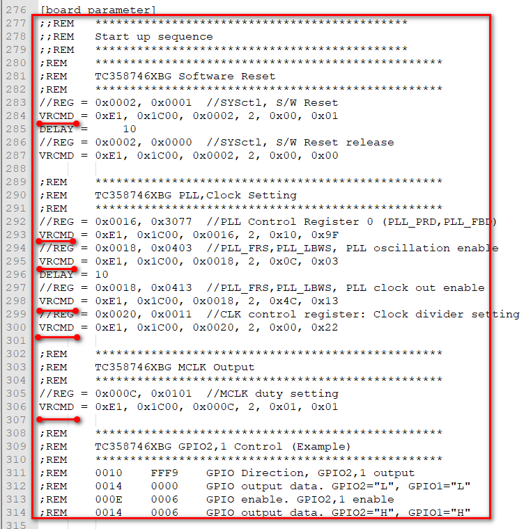
Also, some configuration files may have a large section starting with “VRCMD =“, which is used to configure older MIPI Adapter Boards (UC-489 Rev. C). Some configuration files retain this section for compatibility with older and newer models, but it does not actually work for the newer MIPI Adapter Board (UC-628 Rev. B).
For example:
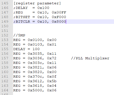
- REG = 0x3035, 0x11 means the address is 16 bits and the data is 8 bits.
- The I2C_MODE and I2C_ADDR at the beginning of the configuration file should be set correctly first.
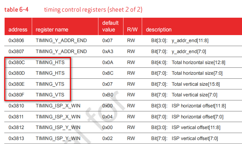
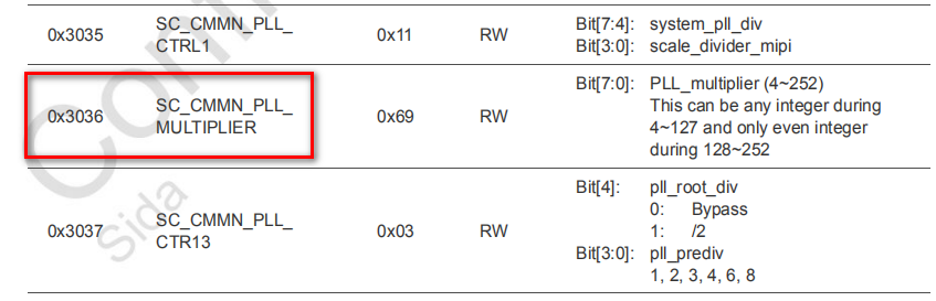
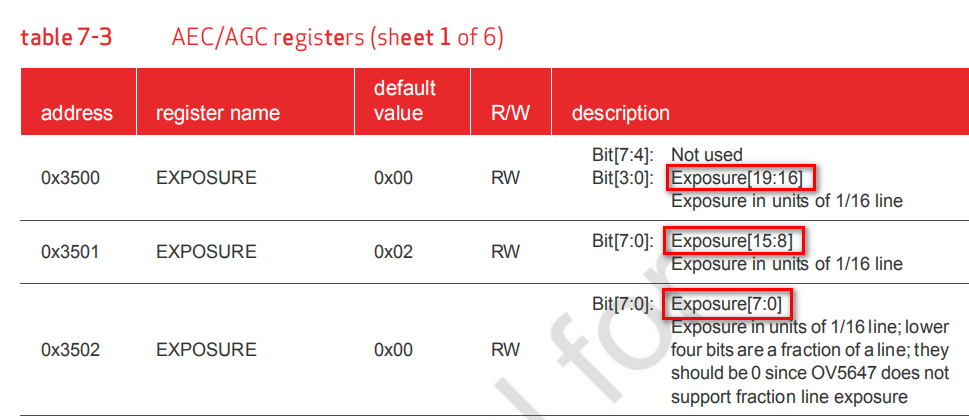
The specific configuration of the camera requires reference to the datasheet. Commonly used registers such as PLL, VTS/HTS, Exposure, Gain, RAW mode, etc.

Modification Examples
The following are a few scenarios for modifying the configuration file for reference.
Change RAW8 to RAW10
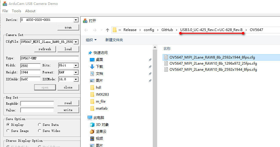
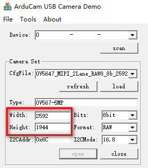
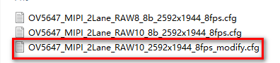
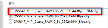
Take the configuration file OV5647_MIPI_2Lane_RAW8_8b_2592x1944_8fps.cfg as an example, now we want to modify it to 2Lane RAW10 2592×1944 configuration, i.e. the number of Lanes and resolution remain the same, just modify the RAW format.
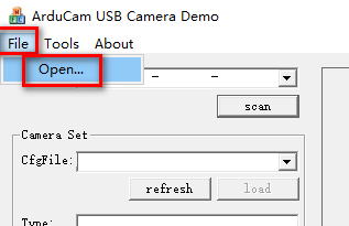
First, make a copy of OV5647_MIPI_2Lane_RAW8_8b_2592x1944_8fps.cfg.
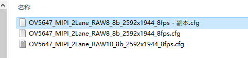
Second, rename the copied file.
Third, open with a text editor (e.g. Notepad++).
Since the camera and resolution are not changed, the [Camera parameter] section does not need to be modified.
In the CPLD configuration, change the 0x0C register value from 0x81 to 0x91.
| Lane channel | RAW Format | 0x0C value |
|---|---|---|
| 1 | RAW8 | 0x80 |
| 2 | RAW8 | 0x81 |
| 4 | RAW8 | 0x82 |
| 1 | RAW10 | 0x90 |
| 2 | RAW10 | 0x91 |
| 4 | RAW10 | 0x92 |
| 1 | RAW12 | 0xA0 |
| 2 | RAW12 | 0xA1 |
| 4 | RAW12 | 0xA2 |
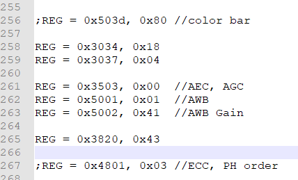
Check the camera manual and find the register for modifying the RAW format.
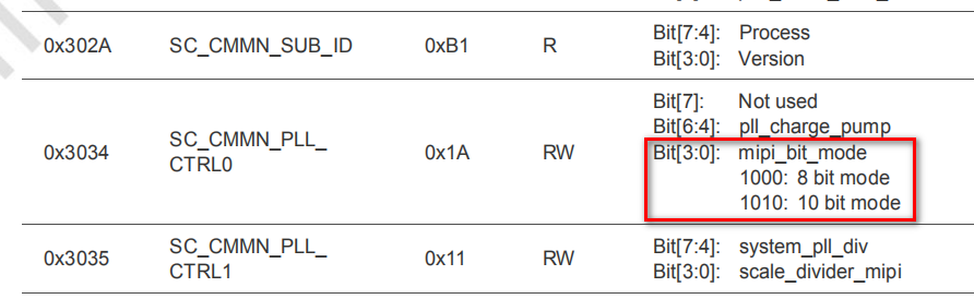
The 0x3034 register defines the RAW format. The default value is 0x1A, which means RAW10; if it is 0x18, it means RAW8.
Then look for 0x3034 in the configuration file, and find it in two places, the last one prevailing.
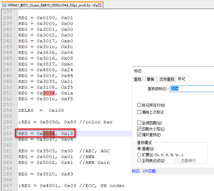
0x3034 current value is 0x18, change it to 0x1A.
Save the modified configuration file.
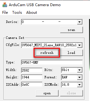
Click 【refresh】 to see the newly created file only in the drop-down list.
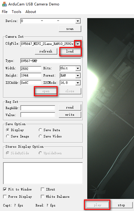
Click 【load】-【open】-【play】 in turn, out normal image.
Click 【Tools】-【Data Info】
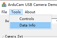
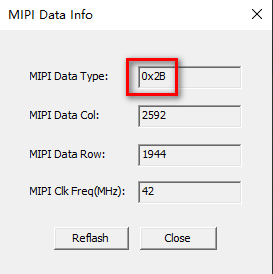
It shows that the DataType parsed by the CPLD is 0x2B, which also indicates that it is indeed in RAW10 format.

Note
1.If the upper computer reports badframe error after RAW8 is changed to RAW10, it may be because the amount of data in one line is increased to 1.25 times, and the HTS is too small, so the HTS needs to be increased to output the image.RAW10 changed to RAW8 without modifying HTS.
2.Some cameras also need to modify the PLL register when the RAW format is modified.
3.Because the upper computer cannot parse RAW10 at present, the CPLD on USB2.0 Camera Shield Rev. E is throwing away the lower two bits of 10bit and turning them into 8bit before uploading, so BIT_WIDTH is set to 8bit. BIT_WIDTH is also set to 8bit for RAW12.
Fix RAW Format and Resolution
The following is how to correct the profile if the number of Lanes is known, but the RAW format and exact resolution are not known ( assuming that the camera output is normal, just not sure that the USB2 Camera Shield is properly configured).
Still take OV5647_MIPI_2Lane_RAW8_8b_2592x1944_8fps.cfg configuration file as an example.
First, make a copy of OV5647_MIPI_2Lane_RAW8_8b_2592x1944_8fps.cfg, then modify this copy file.
Open with a text editor (e.g. Notepad++).
We intentionally changed the SIZE wrong from 2592,1944 to 2500,1900
Change the 0x0C register to 0x91 from 0x81 by mistake as well.
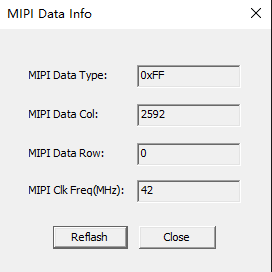
The upper computer loads this configuration file and the error is reported (Bad frame received).

MIPI Data Info information is also abnormal.
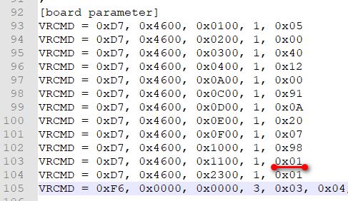
Then, we change the 0x11 register value from 0x07 (or 0x03) to 0x01.
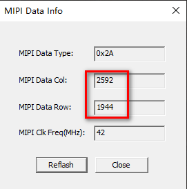
Save, reload, and check the MIPI Data Info.
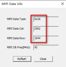
0x2A indicates RAW8 with a resolution of 2592×1944.
Now fix the configuration file:
- change the SIZE to 2592,1944.
- change 0x11 to 0x03.
- change 0x0C to 0x81.
The image will come out normally.
Note
If the camera output is in RAW10 format, after changing 0x11 to 0x01, the Col value in MIPI Data Info at this time is not the column resolution, but the number of rows (WordCount). For example, the following figure shows the result after changing 0x11 to 0x01 on the RAW10 configuration.
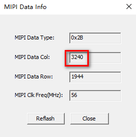
0x2B means it is RAW10, and the amount of RAW10 data is 1.25 times of RAW8, so the column resolution should be 3240/1.25=2592.
Or fix 0x11 and 0x0C first (change 0x11 to 0x03 and 0x0C to 0x91), then check MIPI Data Info (Col and Row are accurate at this point), and finally fix SIZE.