Software SDK and API for Python
1. Introduction
This user guide describes the detail software operation of ArduCAM USB camera shield based on Python SDK library. The latest SDK library and examples can be downloaded from the https://github.com/arducam.
2. USB SDK Library
The ArdCAM USB Python SDK library is designed for both ArduCAM USB2.0 and USB3.0 camera boards. It is binary from the library which composed by .lib and .dll or *.so files. The x86 is compiled for 32bit system and the x64 is compiled for 64bit system.
3. Demo Code
The demo code is provided in source code form to help user to understand the operation the ArduCAM USB camera and Python SDK library. The demo code located in Python folder which supports both Python2 and Python3.
4. ArduCAM APIs
There is a set of API functions that access the ArduCAM USB camera hardware.
4.1.Data Structures
There are important data structures used by the SDK library for the camera configuration.
4.1.1 ArduCamCfg Data Structure Members
| u32CameraType | unsigned long, reserved for future use |
|---|---|
| u32Height | unsigned long, the height of the video stream |
| u32Width | unsigned long, the width of the video stream |
| u8PixelBytes | unsigned char, the number of bytes of one pixel |
| u8PixelBits | unsigned char, the bits depth per pixel |
| emI2cMode | enum type i2c_mode, I2C protocol for the sensor |
| u32I2cAddr | unsigned long, I2C slave address for the sensor |
| u16Vid | unsigned short, the vendor code of the camera |
| usbType | unsigned char, USB camera version |
| emImageFmtMode | enum type format_mode,Image format |
| u32Size | unsigned long, The size of the received data, mainly used for JPG data |
Example:
cfg = {"u32CameraType":0x4D091031,
"u32Width":1280,"u32Height":964,
"usbType":0,
"u8PixelBytes":1,
"u16Vid":0,
"u32Size":0,
"u8PixelBits":8,
"u32I2cAddr": "0x20",
"emI2cMode":3,
"emImageFmtMode":0,
"u32TransLvl":64 }
The SDK library supports 4 different I2C modes. For example I2C_MODE_8_8 is for 8bits register and 8bits register value, I2C_MODE_8_16 is for 8bits register and 16bits register value.
ArducamSDK.I2C_MODE_8_8 = 0
ArducamSDK.I2C_MODE_8_16 = 1
ArducamSDK.I2C_MODE_16_8 = 2
ArducamSDK.I2C_MODE_16_16 = 3
The SDK library supports 7 different Image format modes.
ArducamSDK.FORMAT_MODE_RAW = 0
ArducamSDK.FORMAT_MODE_RGB = 1
ArducamSDK.FORMAT_MODE_YUV = 2
ArducamSDK.FORMAT_MODE_JPG = 3
ArducamSDK.FORMAT_MODE_MON = 4
ArducamSDK.FORMAT_MODE_RAW_D = 5
ArducamSDK.FORMAT_MODE_MON_D = 6
4.2 Function
Function diagram
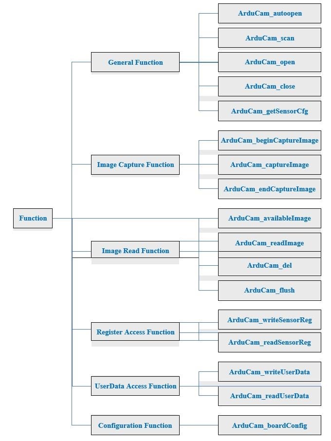
4.2.1 General Function
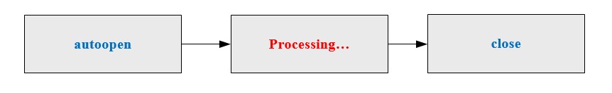
4.2.1.1 Py_ArduCam_autoopen(cfg )
This function is used auto open the supported cameras when it find the first camera on the USB bus, which matched the vendor code of the camera in ArduCamCfg structure.
Param 1: ArduCamCfg structure instance Return vale: error code, handle,cfg
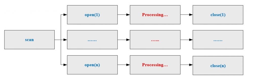
4.2.1.2 Py_ArduCam_scan()
Scan how many supported cameras available on the USB bus, and return the camera index and camera serial number.
Return vale: number of supported cameras,indexs,serials
4.2.1.3 Py_ArduCam_open( cfg,index)
It is commonly used with scan method and open the camera with the camera index. Param 1: ArduCamCfg structure instance
Param 2: index of the camera, handle,cfg Return vale: error code
4.2.1.4 Py_ArduCam_close( handle )
Close the current camera by the camera handle. Param 1: handle to the USB camera instance Return vale: error code
4.2.1.5 Py_ArduCam_getSensorCfg( handle )
Get the configuration parameter of the USB camera instance. Param1: handle to the USB camera instance
Return value: error code,cfg
4.2.1.6 Recommend Operation Procedure
Single Camera
Multiple Cameras
4.2.2 Image Capture Function
4.2.2.1 Py_ArduCam_beginCaptureImage(handle )
Create and prepare the image capture task list. Param 1: handle to the USB camera instance Return value: error code
4.2.2.2 Py_ArduCam_captureImage( handle )
Launch an image capture task.
Param 1: handle to the USB camera instance Return value: error code
4.2.2.3 Py_ArduCam_endCaptureImage( handle )
Destroy the image capture task list.
Param 1: handle to the USB camera instance Return value: error code
4.2.2.4 Recommend Operation Procedure

4.2.3 Image Read Function
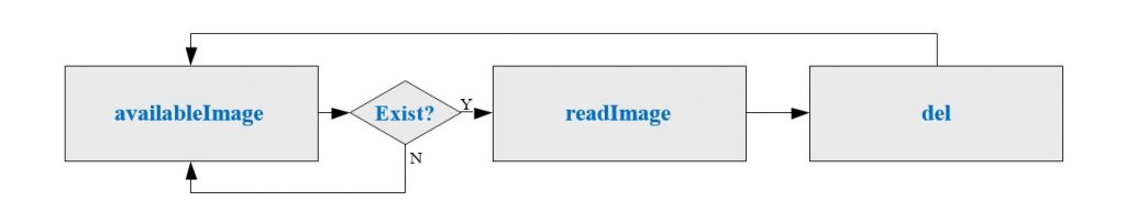
4.2.3.1 Py_ArduCam_availableImage( handle )
Check if the image is available for reading in image FIFO. Param 1: handle to the USB camera instance
Return value: Number of available images
4.2.3.2 Py_ArduCam_readImage( handle)
Read one image data from image FIFO. Param 1: handle to the USB camera instance Return value: error code, data,cfg
4.2.3.3 Py_ArduCam_del( handle )
Delete the image data from image FIFO. Param1: handle to the USB camera instance Return value: error code
4.2.3.4 Py_ArduCam_flush( ArduCamHandle useHandle )
Clear all the image data from image FIFO. Param1: handle to the USB camera instance Return value: error code
4.2.3.5 Recommend Operation Procedure
4.2.4 Sensor Register Access Function
4.2.4.1 Py_ArduCam_writeSensorReg( handle, regAddr, val )
Write the sensor register.
Param 1: handle to the USB camera instance Param 2: the register address to be written Param 3: value to be written
Return value: error code
4.2.4.2 Py_ArduCam_readSensorReg(handle, regAddr )
Read the sensor register.
Param 1: handle to the USB camera instance Param 2: the register address to be read Return value: error code, regValue
4.2.5 User Data Access Function
There are 1024 bytes flash memory for storing user defined data.
4.2.5.1 Py_ArduCam_writeUserData( handle,u16Addr, u8Len,data )
Write data to user region.
Param 1: handle to the USB camera instance
Param 2: user region address to be written, range from 0 ~1023.
Param 3: data length to be written ( length≤32,address+length≤1024) Param 4: data to be written
Return value: error code
4.2.5.2 Py_ArduCam_readUserData( handle, u16Addr, u8Len )
Write data from user region.
Param 1: handle to the USB camera instance
Param 2: user region address to be read, range from 0 ~1023.
Param 3: data length to be read ( length≤32,address+length≤1024) Return value: error code,data
4.2.6 Camera Board Configuration
The board configuration function is used to set correct register or firmware values to hardware for different working mode. See section 5 for detail.
4.2.6.1 Py_ArduCam_setboardConfig( handle, u8Command, u16Value, u16Index, u32BufSize, data )
Write board configuration data.
Param 1: handle to the USB camera instance Param 2: vendor command code
Param 3: vendor command value Param 4: vendor command index Param 5: data buffer size
Param 6: data
Return value: error code
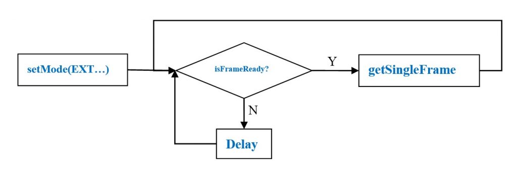
4.2.7 External Trigger
The external trigger mode requires latest hardware and firmware support. If the firmware version does not support external triggering, the following function will return: USB_BOARD_FW_VERSION_NOT_SUPPORT_ERROR
4.2.7.1 Py_ArduCam_setMode(handle,mode)
This function is used to set the working mode between external trigger mode and continuous mode.
Param 1: handle to the USB camera instance
Param 2: mode EXTERNAL_TRIGGER_MODE or CONTINUOUS_MODE
Return value: error code
4.2.7.2 Py_ArduCam_isFrameReady(handle)
This function checks if there is a frame ready to read. Param 1: handle to the USB camera instance
Return value: 1 is ready or 0 is not ready
4.2.7.3 Py_ArduCam_softTrigger(handle)
This function is used to trigger the camera to take image by software rather than from the external trigger input.
Param 1: handle to the USB camera instance Return value: error code
4.2.7.4 Py_ArduCam_getSingleFrame(handle,time_out=1500)
This method can be used to read a single frame with software or external trigger mode. Param 1: handle to the USB camera instance
Param 2: Timeout millisecond default is 1500ms Return value: error code
4.2.7.5 Recommend Operation Procedure
5. Vendor Command Code
The vendor command code is used to configure the hardware or firmware registers. The USB2.0 and USB3.0 vendor command code lists as below:
5.1 USB2.0 Vendor Command Code
| VRCMD Code | Value | Index | Size | Buffer Value | Comment |
|---|---|---|---|---|---|
| 0xD7 | 0x4600 | 0x0100 | 1 | 0x00 | Reset the camera |
| 0xD7 | 0x4600 | 0x0100 | 1 | 0x15 | Enable IR-Cut |
| 0xD7 | 0x4600 | 0x0100 | 1 | 0x25 | Invert the Pixel Clock |
| 0xD7 | 0x4600 | 0x0100 | 1 | 0x45 | Enable JPEG mode |
| 0xD7 | 0x4600 | 0x0100 | 1 | 0x85 | 16bit camera bus |
| 0xF6 | 0x0000 | 0x0000 | 3 | 0x03,0x04,0x0C | Sync 8bit bus mode |
| 0xF6 | 0x0000 | 0x0000 | 3 | 0xCB,0x00,0x0C | Async 8bit bus mode |
| 0xF6 | 0x0000 | 0x0000 | 3 | 0x03, 0x04, 0x09 | Sync 16bit bus mode |
5.2 USB3.0 Vendor Command Code
| VRCMD Code | Value | Index | Size | Buffer Value | Comment |
|---|---|---|---|---|---|
| 0xA3 | 0x0000 | 0x0000 | 0 | NULL | Reset the camera |
| 0xA3 | 0x8000 | 0x0000 | 0 | NULL | Disable IR-Cut |
| 0xA3 | 0x8001 | 0x0000 | 0 | NULL | Enable IR-Cut |
| 0xF3 | 0x0000 | 0x0000 | 0 | NULL | Enable I2C bus |
| 0xF9 | 0x0000 | 0x0000 | 0 | NULL | 8bit camera bus |
| 0xF9 | 0x0001 | 0x0000 | 0 | NULL | 16bit camera bus |
6 Error Code
The error code of the SDK library is defined in the following table.
| ArducamSDK.USB_CAMERA_NO_ERROR | = 0x0000 |
|---|---|
| ArducamSDK.USB_CAMERA_USB_CREATE_ERROR | = 0xFF01 |
| ArducamSDK.USB_CAMERA_USB_SET_CONTEXT_ERROR | = 0xFF02 |
| ArducamSDK.USB_CAMERA_VR_COMMAND_ERROR | = 0xFF03 |
| ArducamSDK.USB_CAMERA_USB_VERSION_ERROR | = 0xFF04 |
| ArducamSDK.USB_CAMERA_BUFFER_ERROR | = 0xFF05 |
| ArducamSDK.USB_CAMERA_NOT_FOUND_DEVICE_ERROR | = 0xFF06 |
| ArducamSDK.USB_CAMERA_I2C_BIT_ERROR | = 0xFF0B |
| ArducamSDK.USB_CAMERA_I2C_NACK_ERROR | = 0xFF0C |
| ArducamSDK.USB_CAMERA_I2C_TIMEOUT | = 0xFF0D |
| ArducamSDK.USB_CAMERA_USB_TASK_ERROR | = 0xFF20 |
| ArducamSDK.USB_CAMERA_DATA_OVERFLOW_ERROR | = 0xFF21 |
| ArducamSDK.USB_CAMERA_DATA_LACK_ERROR | = 0xFF22 |
| ArducamSDK.USB_CAMERA_FIFO_FULL_ERROR | = 0xFF23 |
| ArducamSDK.USB_CAMERA_DATA_LEN_ERROR | = 0xFF24 |
| ArducamSDK.USB_CAMERA_FRAME_INDEX_ERROR | = 0xFF25 |
| ArducamSDK.USB_CAMERA_USB_TIMEOUT_ERROR | = 0xFF26 |
| ArducamSDK.USB_CAMERA_READ_EMPTY_ERROR | = 0xFF30 |
| ArducamSDK.USB_CAMERA_DEL_EMPTY_ERROR | = 0xFF31 |
| ArducamSDK.USB_CAMERA_SIZE_EXCEED_ERROR | = 0xFF51 |
| ArducamSDK.USB_USERDATA_ADDR_ERROR | = 0xFF61 |
| ArducamSDK.USB_USERDATA_LEN_ERROR | = 0xFF62 |
| ArducamSDK.USB_BOARD_FW_VERSION_NOT_SUPPORT_ERROR | = 0xFF71 |