Quick Start
Hardware
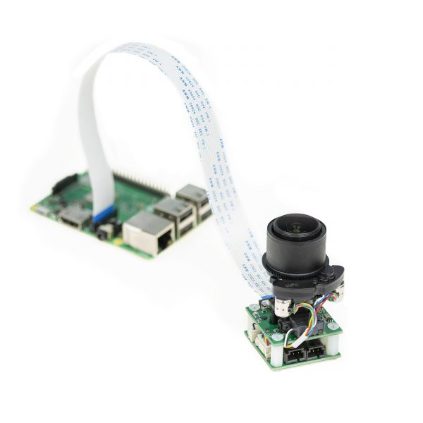
Connection between Camera and Platform
Connect the Camera Module to NVIDIA Jetson with Ribbon Cable
-
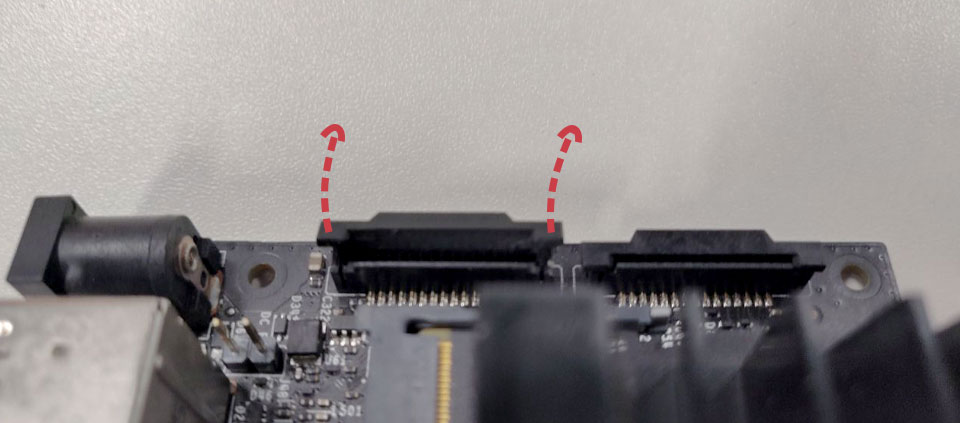
Locate the camera connector (CSI). It’s on the side of the carrier board, opposite to the GPIO pins.
-
Pull up on the plastic edges of the camera port. Do it gently to avoid pulling it off.
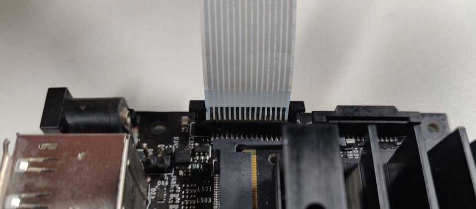
- Push in the camera ribbon. Make sure the contacts are facing the heatsinks. Do not bend the flex cable, and make sure it’s firmly inserted into the bottom of the connector.
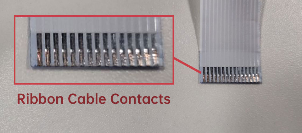 Ribbon Cable Contacts – 15pin-15pin
 Silver Contacts facing inside to the heatsinks
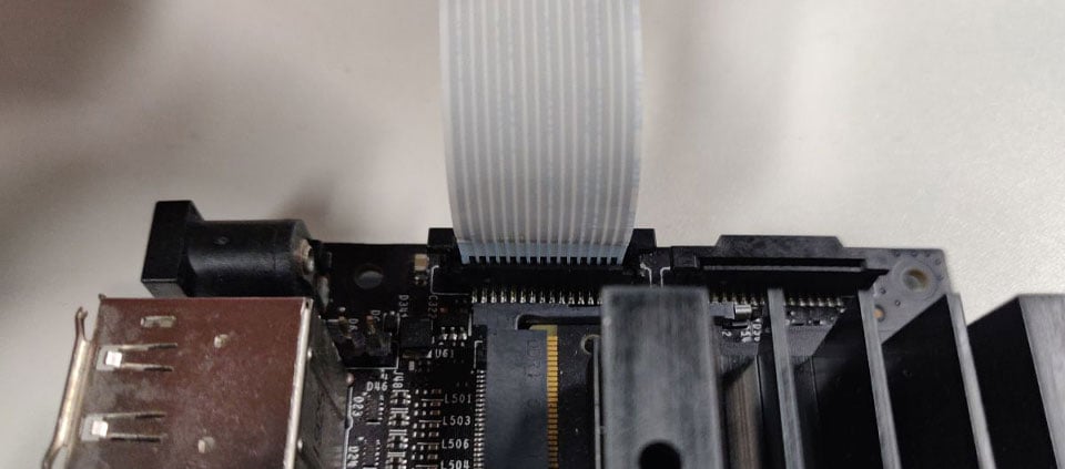 Ribbon cable fully inserted to the bottom of the CSI connector
- Push the plastic connector down. Do it while holding the flex cable until the connector is back in place.
Connect the Servo Motors
The metal base with servos and jumper wire are not included in the package.
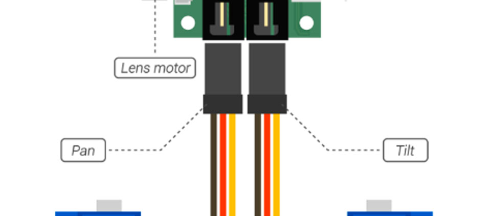
Connect the 3-pin plug of the servo motors to the two sockets of the driver controller board.
-
The left socket is for the pan servo, and the right socket is for the tilt servo.
-
Note the color of the 3-pin plug. It’s brown, red and yellow from left to right.
Servo plug connection:
Connect the driver controller board with jumpers
Please note that
The metal base with servos and jumper wire are not included in the package.
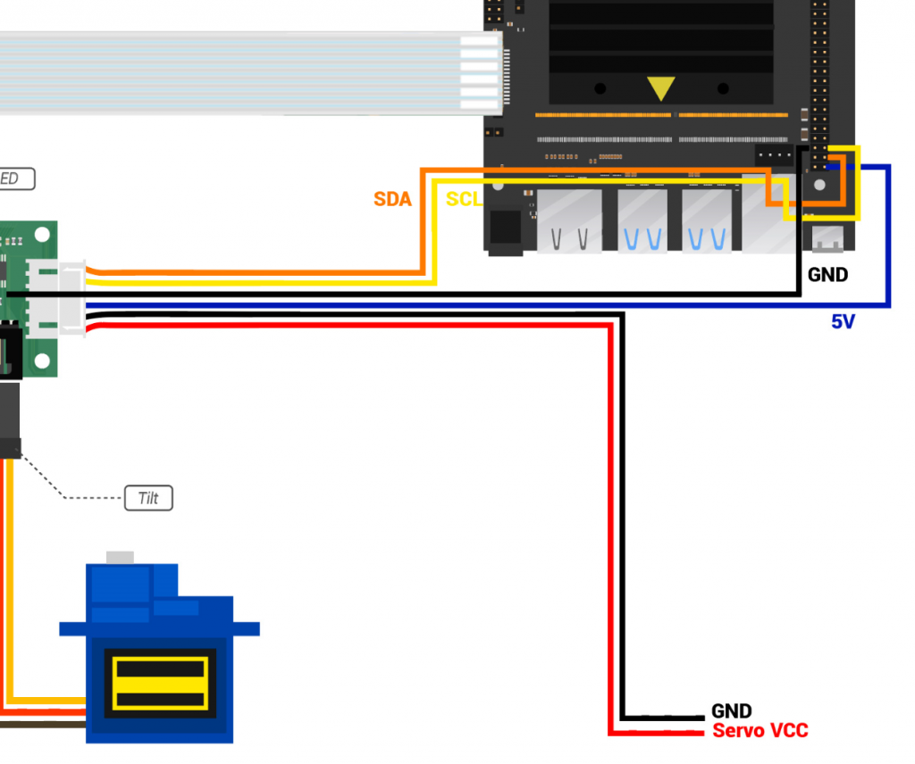
The jumpers of the driver controller board can be separated into 3 pairs, and they are mainly for two purposes: I2C control signals and power supplies.
- The 1st pair connects to external power, with Pin#1 being Servo VCC and Pin#2 GND.
- The 2nd pair connects to the RPi’s GPIO pins for power, with Pin#3 being 5V and Pin#4 GND.
- The 3rd pair also connects to the Jetson’s GPIO pins for I2C, with Pin#5 being SCL and Pin#6 SDA.
Driver controller board jumpers connection:
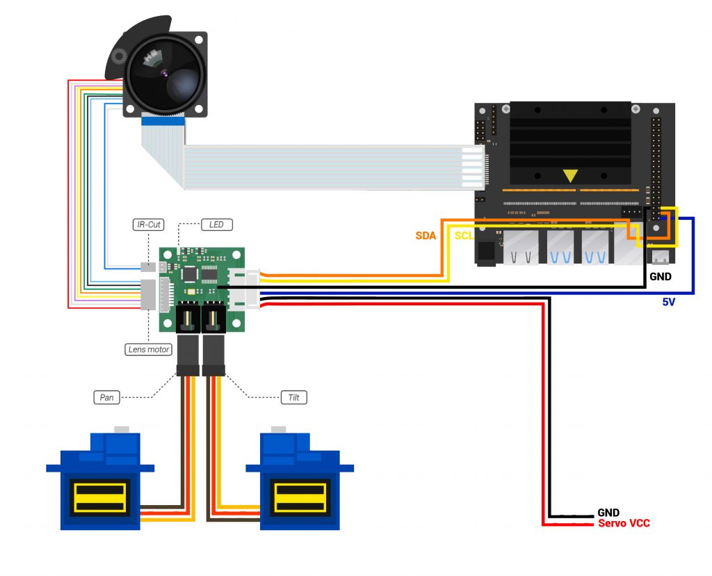
Please note that In this illustrator, the different colors of the jumper wires are just to make it easier to distinguish them from each other. The order of those colors varies from item to item, so it may not match the one you’ve received. Therefore, instead of its color, you should rely on the position of the wire to correctly connect the jumpers.
After you finish the hardware assemble process, refer to Picture 3 to review the connections you’ve made.
Connection Overview
Software
Supported Platforms and JetPack L4T versions
Please refer to the following doc for specific supported Platforms and JetPack versions:
Supported Platforms and JetPack Version - Arducam Camera for NVIDIA Jetson
For IMX219 PTZ Camera
| Product Image | SKU | Pin/Connect Type | Resolution | Features | Field of View(HxV) | Focus Type | IR Sensitivity |
|---|---|---|---|---|---|---|---|
 |
B0167B8 | 15pin/Bottom | 8MP | Servo Steer | H(67°~18°) x V(49°~13°) | Motorized Focus | Motorized IR Cut Filter |
| B01678MP | PTZ Zoom |
-
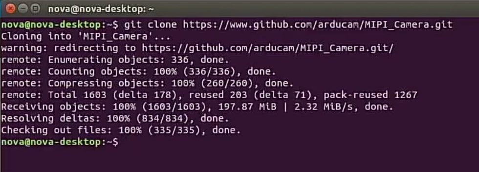
Download the demo code
git clone https://www.github.com/arducam/MIPI_Camera.git
-
Install Dependency
sudo apt install python-smbus
-
Enter the folder
cd MIPI_Camera/Jetson/JetsonNano_PTZ/
-
Run the demo code
python FocuserExample.py

Note
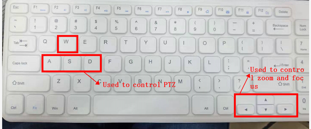
Note that after opening the program, please press the 't' key and wait for about 8 seconds. The mode will switch from 'Fix' to 'Adjust'. At Adjust Mode, you can use the keyboard to control zoom, focus, IR-CUT, etc.
The default mode is "Fix" Mode. As long as the power supply is not turned off, the mode will be saved. If the power is off, the mode will be initialized.
The figure below shows that the Adjust mode UI, and the PTZ camera Kit can be manually controlled at this mode

Focus Eample Demo
- Focuser.py
- zoom-lens basic control component.
- AutoFocus.py
- Provide two autofocus methods are available, depending on Focuser.py, opencv, picamera
- Use the sudo apt-get install python-opencv command to install opencv.
- AutoFocusExample.py
- Example of using autofocus, depending on AutoFocus.py
- FocuserExample.py
- zoom-lens controller.
For IMX477 PTZ Camera
| Product Image | SKU | Pin/Connect Type | Resolution | Features | Field of View(HxV) | Focus Type | IR Sensitivity |
|---|---|---|---|---|---|---|---|
 |
B0167B12 | 15pin/22pin | 12MP | Servo Steer | H(96°-33°) x V(72°-24°) | ||
| B016712MP | PTZ Zoom |
-
Demo
-
Driver Installation
Step 1. Download the bash scripts
cd ~
wget https://github.com/ArduCAM/MIPI_Camera/releases/download/v0.0.3/install_full.sh
Step 2. Install the driver
chmod +x install_full.sh
./install_full.sh -m imx477
-
Download the demo code
git clone https://www.github.com/arducam/MIPI_Camera.git

-
Install Dependency
sudo apt install python-smbus
-
Enter the folder
cd MIPI_Camera/Jetson/JetsonNano_PTZ/
-
Run the demo code
python FocuserExample.py
Note
Note that after opening the program, please press the 't' key and wait for about 8 seconds. The mode will switch from 'Fix' to 'Adjust'. At Adjust Mode, you can use the keyboard to control zoom, focus, IR-CUT, etc.
The default mode is "Fix" Mode. As long as the power supply is not turned off, the mode will be saved. If the power is off, the mode will be initialized.
The figure below shows that the Adjust mode UI, and the PTZ camera Kit can be manually controlled at this mode