MT9D111 with Arducam shield for Arduino UNO
The Arduino Uno is an open-source microcontroller board based on the Microchip ATmega328P microcontroller and developed by Arduino.cc.
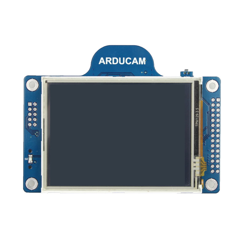
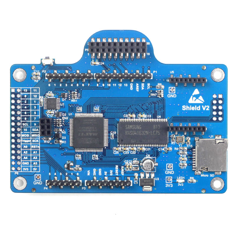
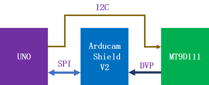
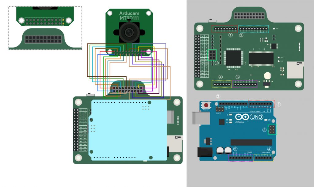
MT9D111 Camera Module has a parallel interface, so it can not be connected to Arduino UNO directly. As is known to us all, the SRAM of Arduino UNO(2KB-ATmega328P) is too small to store one image, and the clock frequency of MT9D111 is much higher than the processing capacity of the microcontroller-ATmega328P. However, the Arducam shield can convert the parallel interface to the SPI interface, so that the parallel interface camera module can be used on Arduino UNO indirectly. By the way, maybe you are interested in the Arducam SPI camera that can be directly connected to Arduino or another process like ESP8266, ESP32, etc. Please click Arducam Shield Mini 2MP Plus and Arducam Shield Mini 5MP Plus to learn more.
In summary, if you want to use the MT9D111 camera module on Arduino UNO, the shield is an essential part of you. What is the shield? you can learn more from the DOC.
This document will show you how to use Arducam MT9D111 with Shield to capture JPEG and BMP format images on Arduino UNO.
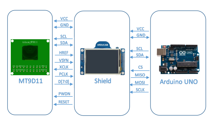
1.Hardware
2.Software
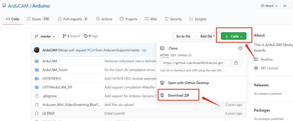
2.1 Download source code package
Please refer to google
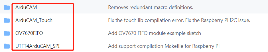
Unzip the source code package and copy the four tool packages to the Arduino-libraries path.
2.2 Quick start guide
You can follow the DOC.
Step 1:
Open the memorysaver.h file from Arduino\libraries\ArduCAM.
Step 2:
You should not only uncomment the line ” #define ARDUCAM_SHIELD_V2″ , but also uncomment the line ”#define MT9D111B_CAM” or ''#define MT9D111A_CAM''.
//Step 1: select the hardware platform, only one at a time
//#define OV2640_MINI_2MP
//#define OV3640_MINI_3MP
//#define OV5642_MINI_5MP
//#define OV5642_MINI_5MP_BIT_ROTATION_FIXED
#define OV2640_MINI_2MP_PLUS
//#define OV5642_MINI_5MP_PLUS
//#define OV5640_MINI_5MP_PLUS


//#define ARDUCAM_SHIELD_REVC
#define ARDUCAM_SHIELD_V2


//Step 2: Select one of the camera module, only one at a time
#if (defined(ARDUCAM_SHIELD_REVC) || defined(ARDUCAM_SHIELD_V2))
    //#define OV7660_CAM
    //#define OV7725_CAM
    //#define OV7670_CAM
    //#define OV7675_CAM
    //#define OV2640_CAM
    //#define OV3640_CAM
    //#define OV5642_CAM
    //#define OV5640_CAM

    //#define MT9D111A_CAM
    #define MT9D111B_CAM
    //#define MT9M112_CAM
    //#define MT9V111_CAM
    //#define MT9M001_CAM
    //#define MT9V034_CAM
    //#define MT9M034_CAM
    //#define MT9T112_CAM
    //#define MT9D112_CAM
Note
MT9D111A and MT9D111B have different sensor address: -MT9D111A is 0xbe -MT9D111B is 0x90
2.3 Example Sketches
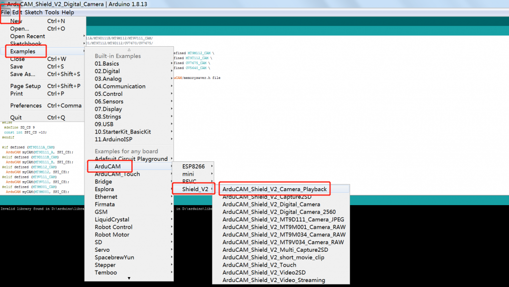
2.3.1 ArduCAM_Shield_V2_Camera_Playback
Please follow the figure to open up the example of ArduCAM_Shield_V2_Camera_Playback
- Compile and upload to your Arduino.
- Please check if you have inserted the SD card.
- Press button1 on the shield to Capture.
- The captured images will be stored on the SD card.
Note
-Why the LCD screen can display real-time streaming?
BMP file is actually RGB565 save as the BMP code including RGB565 and BMP Hard, so the LCD screen can
display the real-time streaming directly.
-Why does the BMP image stored in the SD card rotate 180 degrees?
This is related to the storage method of the main control chip.

BMP Format from ArduCAM_Shield_V2_Camera_Playback
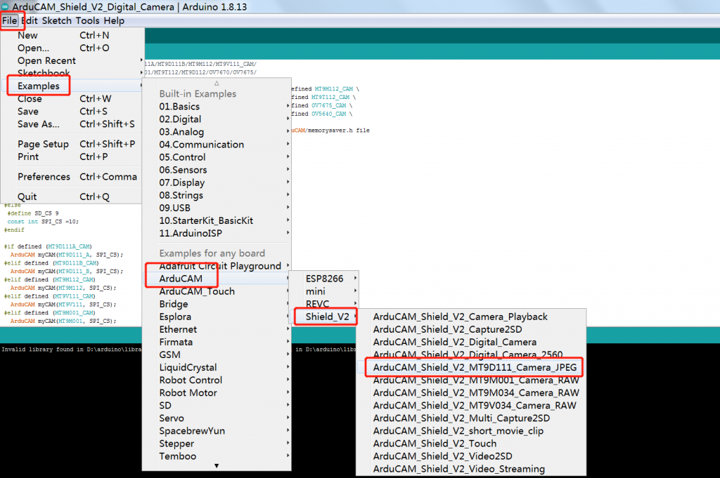
2.3.2 ArduCAM _shield_V2_MT9D111_Camera_JPEG
Please follow the figure to open up the example of ArduCAM _shield_V2_MT9D111_Camera_JPEG.
- Compile and upload to your Arduino.
- Please check if you have inserted the SD card.
- Press button1 on the shield to Capture.
- The captured images will be stored on the SD card.

JPEG Format from ArduCAM _shield_V2_MT9D111_Camera_JPEG
Note
-Why the LCD screen cannot display real-time streaming?
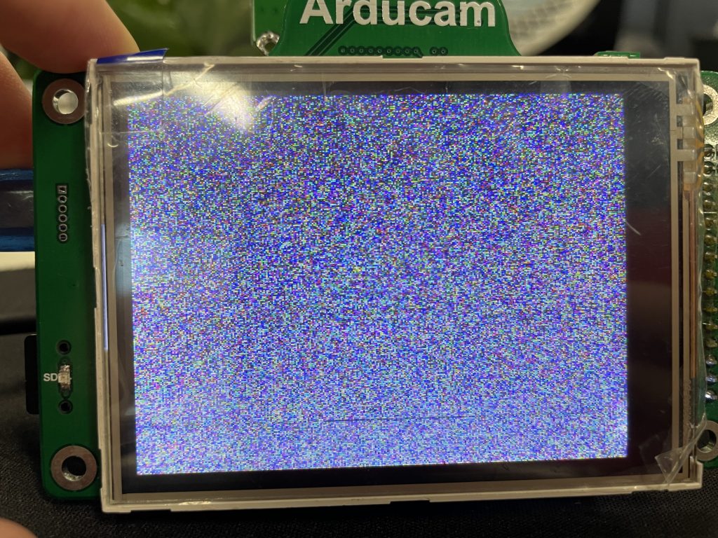 LCD screen only supports RGB565 format image, JPEG is an image after encoding. The data is not real-time image data and needs to be displayed after decoding by a decoder, so it cannot be displayed directly on the RGB screen.