Software SDK and API for C/C++
1. Introduction
This user guide describes the detail software operation of ArduCAM USB camera shield based on SDK library. The latest SDK library and examples can be downloaded from arducam github.
There are lots of hardware platform supported, please find the corresponding SDK folder for your platform.
For Windows the camera driver should be installed manually. Due to the driver signature issue, you have to disable the driver signature reinforcement manually.
2. USB SDK Library
The ArdCAM USB SDK library is designed for both ArduCAM USB2.0 and USB3.0 camera boards. It is binary from library which composed by .lib and .dll or *.so files. The x86 is compiled for 32bit system and the x64 is compiled for 64bit system.
3. Demo Code
The demo code is provided in source code form to help user to understand the operation the ArduCAM USB camera and C/C++ SDK library. The demo code located in Cpp folder which is based on OpenCV. For Windows there is another GUI source project provided which is created with Microsoft Visual Studio 2008 and based on MFC framework, the main files are described as follows.
3.1 Thread.cpp
The Thread.cpp is used to create different tasks to polling the hardware when data is ready to receive and process. Four main tasks should be created to avoid data loss on the hardware side. _FrameCaptureThread : the thread is used to receive the image data from the camera board. _FrameReadThread: the thread to read image data from the SDK library frame buffer.
3.2 USBTestDlg.cpp
The USBTestDlg.cpp is used to handle GUI operation of the demo project. It handles the button click actions, register read/write access, RAW to RGB image processing, display real time video and etc.
3.3 CommonTools.cpp
The CommonTools.cpp is used to provide several common functions, such as conversion between number and ASCII code, the creation of file name and etc.
4. ArduCAM APIs
There are a set of API functions that access to the ArduCAM USB camera hardware.
4.1 Data Structures
There is important data structures used by the SDK library for the camera configuration.
4.1.1 ArduCamCfg Data Structure Members
u32CameraType: unsigned long, reserved for future use.
u32Height: unsigned long, the height of the video stream
u32Width: unsigned long, the width of the video stream
u8PixelBytes: unsigned char, the number of bytes of one pixel
u8PixelBits: unsigned char, the bits depth per pixel
emI2cMode: enum type i2c_mode, I2C protocol for the sensor
u32I2cAddr: unsigned long, I2C slave address for the sensor
u16Vid: unsigned short, the vendor code of the camera
usbType: unsigned char, USB camera version
emImageFmtMode: enum type format_mode,Image format
u32Size: unsigned long, The size of the received data, mainly used for JPG data Definition:
typedef struct
{
Uint32 u32CameraType;
Uint16 u16Vid;
Uint32 u32Width;
Uint32 u32Height;
Uint8 u8PixelBytes;
Uint8 u8PixelBits;
Uint32 u32I2cAddr;
Uint32 u32Size;
Uint8 usbType;
i2c_mode emI2cMode;
format_mode emImageFmtMode;
Uint32 u32TransLvl;
}ArduCamCfg;
The SDK library support 4 different I2C modes. For example I2C_MODE_8_8 is for 8bits register and 8bits register value, I2C_MODE_8_16 is for 8bits register and 16bits register value.
typedef enum {
I2C_MODE_8_8 = 0,
I2C_MODE_8_16 = 1,
I2C_MODE_16_8 = 2,
I2C_MODE_16_16 = 3
}i2c_mode;
The SDK library support 7 different Image format modes.
typedef enum{
FORMAT_MODE_RAW = 0,
FORMAT_MODE_RGB = 1,
FORMAT_MODE_YUV = 2,
FORMAT_MODE_JPG = 3,
FORMAT_MODE_MON = 4,
FORMAT_MODE_RAW_D = 5,
FORMAT_MODE_MON_D = 6,
}format_mode;
4.1.2 ArduCamIndexinfo Data Structure Members
u8UsbIndex: Uint8, USB interface index
u8SerialNum[16]: Uint8[], USB camera serial number
The ArduCamIndexinfo data structure is useful when multiple cameras connected, it helps to find the corresponding camera with index and serial number.
4.2 Functions
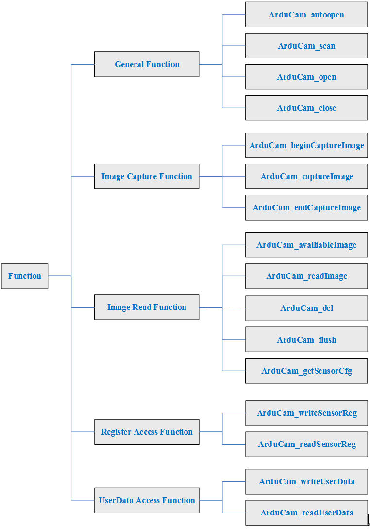
4.2.1 General Function
4.2.1.1 unsigned int ArduCam_autoopen( ArduCamHandle &useHandle, ArduCamCfg* useCfg )
This function is used auto open the supported cameras when it find the first camera on the USB bus, which matched the vendor code of the camera in ArduCamCfg structure.
Param 1: handle to the USB camera instance
Param 2: ArduCamCfg structure instance
Return vale: error code
4.2.1.2 unsigned int ArduCam_scan( ArduCamIndexinfo* pstUsbIdxArray )
Scan how many supported cameras available on the USB bus, and record the camera index and camera serial number in Param 1.
Param 1: list of the supported ArduCAM USB camera
Return vale: number of supported cameras
4.2.1.3 unsigned int ArduCam_open( ArduCamHandle &useHandle, ArduCamCfg* useCfg, unsigned long usbIdx )
It is commonly used with scan method and open the camera with the camera index.
Param 1: handle to the USB camera instance
Param 2: ArduCamCfg structure instance
Param 3: index of the camera
Return vale: error code
4.2.1.4 unsigned int ArduCam_close( ArduCamHandle useHandle )
Close the current camera by the camera handle.
Param 1: handle to the USB camera instance
Return vale: error code
4.2.1.5 unsigned int ArduCam_getSensorCfg( ArduCamHandle useHandle, ArduCamCfg* useCfg )
Get the configuration parameter of the USB camera instance.
Param1: handle to the USB camera instance
Param1: pointer of configuration parameter structure
Return value: error code
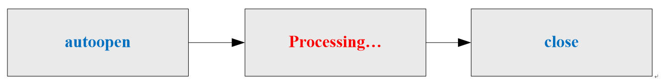
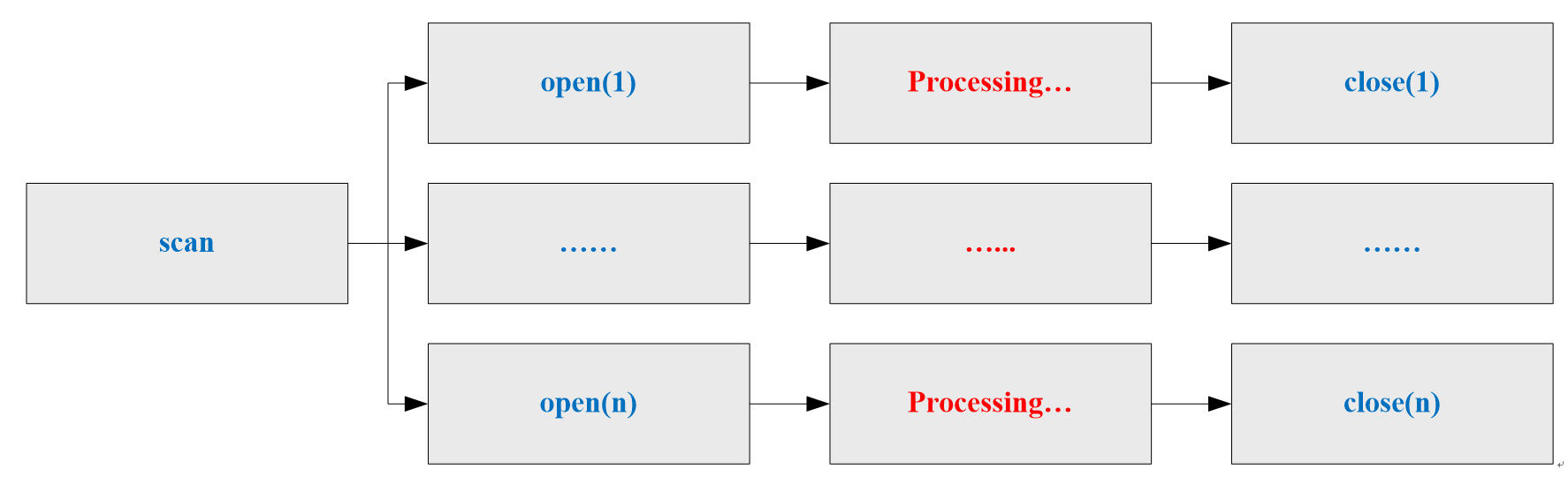
4.2.1.6 Recommend Operation Procedure
Single Camera:
Multiple Cameras:
4.2.2 Image Capture Function
4.2.2.1 unsigned int ArduCam_beginCaptureImage( ArduCamHandle useHandle )
Create and prepare the image capture task list.
Param 1: handle to the USB camera instance
Return value: error code
4.2.2.2 unsigned int ArduCam_captureImage( ArduCamHandle useHandle )
Launch an image capture task.
Param 1: handle to the USB camera instance
Return value: error code
4.2.2.3 unsigned int ArduCam_endCaptureImage( ArduCamHandle useHandle )
Destroy the image capture task list.
Param 1: handle to the USB camera instance
Return value: error code
4.2.2.4 Recommend Operation Procedure

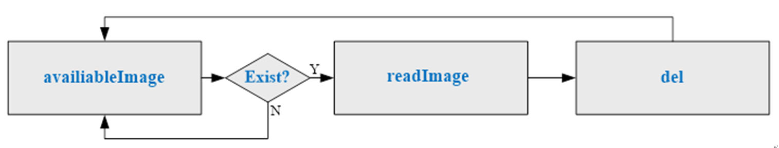
4.2.3 Image Read Function
4.2.3.1 unsigned int ArduCam_availableImage( ArduCamHandle useHandle )
Check if the image is available for reading in image FIFO.
Param 1: handle to the USB camera instance
Return value: error code
4.2.3.2 unsigned int ArduCam_readImage( ArduCamHandle useHandle, unsigned char* &pu8FrameData )
Read one image data from image FIFO.
Param 1: handle to the USB camera instance
Param 2: image data pointer
Return value: error code
4.2.3.3 unsigned int ArduCam_del( ArduCamHandle useHandle )
Delete the image data from image FIFO.
Param1: handle to the USB camera instance
Return value: error code
4.2.3.4 unsigned int ArduCam_flush( ArduCamHandle useHandle )
Clear all the image data from image FIFO.
Param1: handle to the USB camera instance
Return value: error code
4.2.3.5 unsigned int ArduCam_getSensorCfg( ArduCamHandle useHandle, ArduCamCfg* useCfg )
Get the configuration parameter of the USB camera instance.
Param1: handle to the USB camera instance
Param1: pointer of configuration parameter structure
Return value: error code
4.2.3.6 Recommend Operation Procedure
4.2.4 Sensor Register Access Function
4.2.4.1 unsigned int ArduCam_writeSensorReg( ArduCamHandle useHandle, unsigned long regAddr, unsigned long val )
Write the sensor register.
Param 1: handle to the USB camera instance
Param 2: the register address to be written
Param 3: value to be written
Return value: error code
4.2.4.2 unsigned int ArduCam_readSensorReg( ArduCamHandle useHandle, unsigned long regAddr, unsigned long* pval )
Read the sensor register.
Param 1: handle to the USB camera instance
Param 2: the register address to be read
Param 3: read value
Return value: error code
4.2.5 User Data Access Function
There are 1024 bytes flash memory for storing user defined data.
4.2.5.1 unsigned int ArduCam_writeUserData( ArduCamHandle useHandle, unsigned short u16Addr, unsigned char u8Len, unsigned char* pu8Data )
Write data to user region.
Param 1: handle to the USB camera instance
Param 2: user region address to be written, range from 0 ~1023.
Param 3: data length to be written ( length≤32,address+length≤1024)
Param 4: data pointer to be written
Return value: error code
4.2.5.2 unsigned int ArduCam_readUserData( ArduCamHandle useHandle, unsigned short u16Addr, unsigned char u8Len, unsigned char* pu8Data )
Write data from user region.
Param 1: handle to the USB camera instance
Param 2: user region address to be read, range from 0 ~1023.
Param 3: data length to be read ( length≤32,address+length≤1024)
Param 4: data pointer for read data.
Return value: error code
4.2.6 Camera Board Configuration
The board configuration function is used to set correct register or firmware values to hardware for different working mode. And also be called vendor command, VRCMD in the config file.
4.2.6.1 unsigned int ArduCam_setboardConfig( ArduCamHandle useHandle, unsigned char u8Command, unsigned short u16Value, unsigned short u16Index, unsigned int u32BufSize, unsigned char*pu8Buf )
Write board configuration data.
Param 1: handle to the USB camera instance
Param 2: vendor command code
Param 3: vendor command value
Param 4: vendor command index
Param 5: data buffer size
Param 6: data buffer pointer
Return value: error code
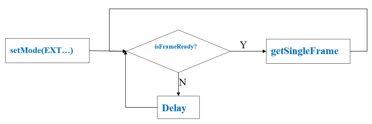
4.2.7 External Trigger
Basically the extenral trigger is only effective given the camera module supports external trigger input such as global shutter camera modules. User can feed proper external trigger signal to these camera module, and for the USB camera shield side just listening the incoming frames (using continuous mode).
For latest USB2 camera shield, it has an advance mode that supports capture only one frame right after the external input trigger, no matter it is rolling shutter or global shutter camera. It only take. This external trigger mode requires latest hardware and firmware support. If the firmware version does not support external triggering, the following function will return:
USB_BOARD_FW_VERSION_NOT_SUPPORT_ERROR
4.2.7.1 unsigned int ArduCam_setMode(ArduCamHandle handle,int mode)
This function is used to set the working mode between external trigger mode and continuous mode.
Param 1: handle to the USB camera instance
Param 2: mode EXTERNAL_TRIGGER_MODE or CONTINUOUS_MODE
Return value: error code
4.2.7.2 unsigned int ArduCam_isFrameReady(ArduCamHandle handle)
This function checks if there is a frame ready to read.
Param 1: handle to the USB camera instance
Return value: 1 is ready or 0 is not ready
4.2.7.3 unsigned int ArduCam_softTrigger(ArduCamHandle handle)
This function is used to trigger the camera to take image by software rather than from the external trigger input.
Param 1: handle to the USB camera instance
Return value: error code
4.2.7.4 unsigned int ArduCam_getSingleFrame(ArduCamHandle handle,int time_out=1500)
This method can be used to read a single frame using software or external hardware trigger. Please note that the external trigger pin is only available on USB2 camera shield and global shutter camera modules. This function only returns after one frame is captured either through software trigger or hardware trigger.
Param 1: handle to the USB camera instance
Param 2: Timeout millisecond default is 1500ms
Return value: error code
4.2.7.5 Recommend Operation Procedure