USB3.0 Camera Shield Datasheet
Introduction
Arducam series USB camera shield is a general purpose USB camera control board for PC and embedded signal board computer. It hides the complex nature of the camera and provides the plug and play camera control interface as well as the ready to use SDK library and demo software source code. The Arducam supports variety camera modules from 0.3MP to 21MP or even higher.
Arducam USB3 camera shield is the latest USB3.0 camera shields, it offers the improved performance and enhanced functions than the previous USB2.0 camera shield. It not only supports high resolution and high frame rate image sensors, but also supports stereoscopy camera and IRCUT control feature. With the given camera configuration files, user can switch between different cameras without any effort. It is the ideal solution for camera evaluation/testing, robot/drone, IoT, machine vision and scientific applications.
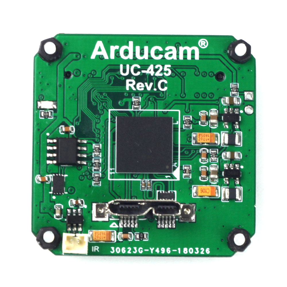
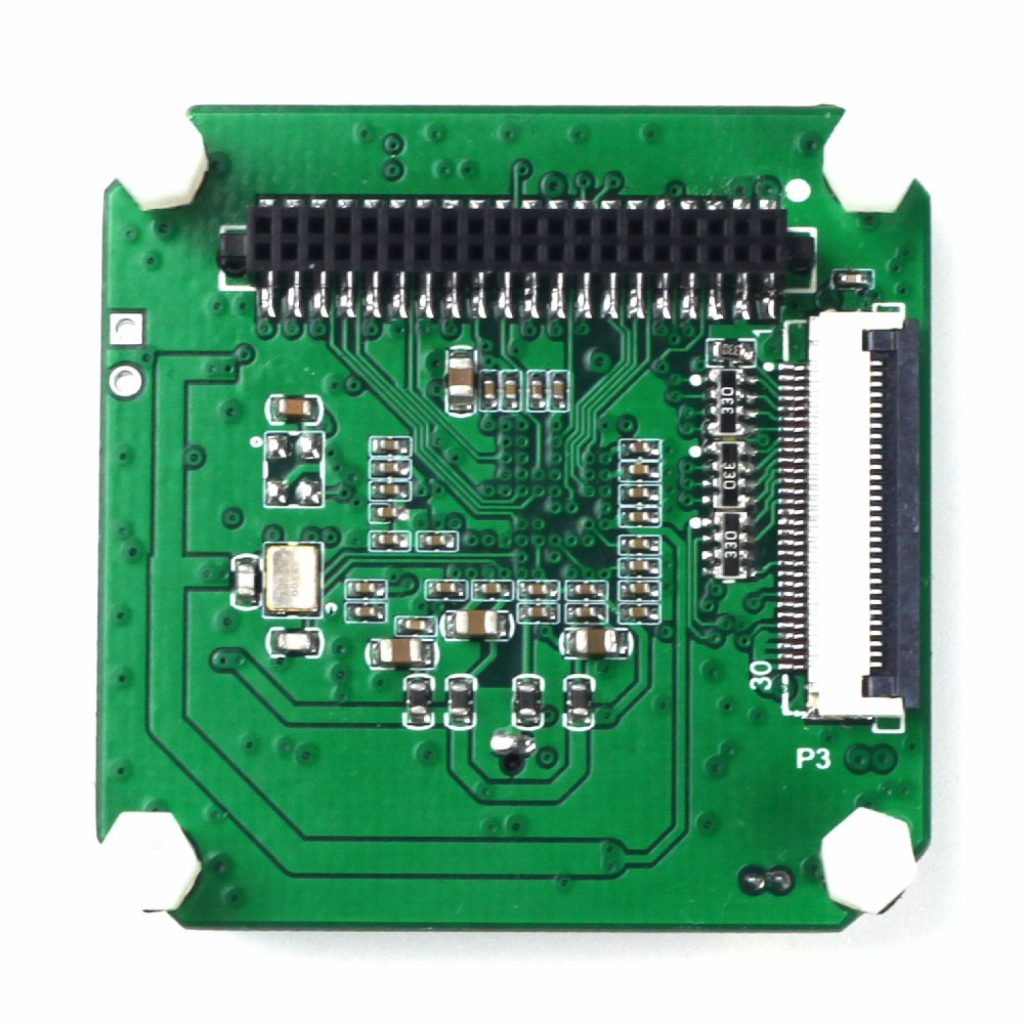
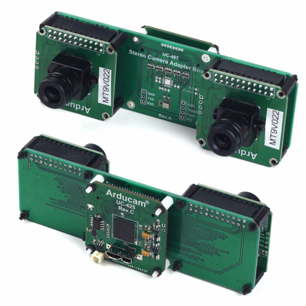
Figure 1 Arducam USB3 Camera Shield
Application
- IoT cameras
- Robot cameras
- Wildlife cameras
- Machine vision
- Scientific cameras
Features
- Support any parallel image sensors (need proper register settings)
- Support 8/10/12/14/16 bit pixel color depth
- Support Stereoscopy mode for dual camera system
- Build-in IRCUT control
- Need extra MIPI to parallel adapter board for supporting MIPI interface sensors (see Table1)
- Provide free binary SDK library and demo software source code, please visit github.com/Arducam
- Fully customizable and can be ported to any hardware platform and software OS
Table 1 Featured Camera Modules Supported
| Resolution | Frame Rate | Camera Module | Sensor Vendor |
|---|---|---|---|
| 0.3MP | 100fps | OV7251 (MIPI) | Omnivision |
| 0.3MP | 60fps | MT9V022/MT9V034 | Aptina |
| 1MP | 120fps | OV9281(MIPI) | Omnivision |
| 2MP | 60fps | OV2311/OG02B10(MIPI) | Omnivision |
| 1.2MP | 50fps | AR0134/AR0135 | Aptina |
| 5MP | 15fps | OV5647 (MIPI) | Omnivision |
| 5MP | 30fps | AR0521 | ONSemi |
| 9MP | 7fps | MT9N001 | Aptina |
| 10MP | 6fps | MT9J001/MT9J003 | Aptina |
| 14MP | 5fps | MT9F002 | Aptina |
| 13MP | 5fps | OV13850 (MIPI) | Omnivision |
| 13MP | 12fps | IMX135(MIPI) | Sony |
| 16MP | 10fps | IMX298(MIIPI) | Sony |
| 18MP | 8fps | AR1820HS(MIPI) | ONSemi |
| 21MP | 5fps | IMX230(MIPI) | Sony |
Key Specifications
- Bandwidth: 5-Gbps USB3.0 PHY
- Camera Databus: 16bit@100MHz
- I/O Voltage Standard: 3.3V
- Connector: Micro-USB3.0
- Size: 40 x 40 mm
- Weight: 10g
- Power Consumption: 5V/300mA
- Operation Temperature: -10℃~+55℃
Pin Definition
Figure 2 shows the connectors of the USB3 camera shield. There are one Micro-USB3.0 connector which can be connected to USB3.0 host controller, and one connector for motorized IR-Cut filter for both daylight and night vision. There are two camera interface on the bottom of the board, one for 8bit camera data bus and the other for 16bit camera data bus. The pin out definition see Table 2 and Table 3.
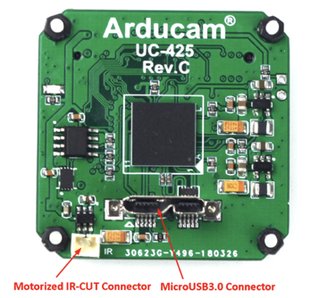
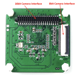
Figure2 USB3 camera shield connectors
The 8bit camera interface is the primary camera interface which is used for Arducam standard camera breakout board with 30pin ribbon cable. Although the camera breakout board might has more than 8bit data bus, only the upper 8bit connected to the USB camera shield through this FPC connector.
Table 2 8-bit Camera Interface Pin Definition
(Connector Part Number: Hirose FH28D-30S-0.5SH(05))
| Pin No. | PIN NAME | TYPE | DESCRIPTION |
|---|---|---|---|
| 1 | GND | Ground | Power ground |
| 2 | Reserved | NC | |
| 3 | Reserved | NC | |
| 4 | VSYNC | Input | Active High: Frame Valid; indicates active frame |
| 5 | HREF | Input | Active High: Line/Data Valid; indicates active pixels |
| 6 | DOUT11 | Input | Camera Pixel Data Input 11 (MSB) |
| 7 | DOUT10 | Input | Camera Pixel Data Input 10 |
| 8 | DOUT9 | Input | Camera Pixel Data Input 9 |
| 9 | DOUT8 | Input | Camera Pixel Data Input 8 |
| 10 | DOUT7 | Input | Camera Pixel Data Input 7 |
| 11 | DOUT6 | Input | Camera Pixel Data Input 6 |
| 12 | DOUT5 | Input | Camera Pixel Data Input 5 |
| 13 | GND | Ground | Power ground |
| 14 | DOUT4 | Input | Camera Pixel Data Input 4 (LSB) |
| 15 | DOUT3 | Input | Camera Pixel Data Input 3 (Unconnected) |
| 16 | DOUT2 | Input | Camera Pixel Data Input 2 (Unconnected) |
| 17 | DOUT1 | Input | Camera Pixel Data Input 1 (Unconnected) |
| 18 | DOUT0 | Input | Camera Pixel Data Input 0 (Unconnected) |
| 19 | Reserved | NC | |
| 20 | PCLK | Input | Pixel Clock output from Camera |
| 21 | SCL | Output | Two-Wire Serial Interface Clock |
| 22 | SDATA | Bi-directional | Two-Wire Serial Interface Data I/O |
| 23 | RST | Output | Sensor reset signal, active low |
| 24 | GND | Ground | Power ground |
| 25 | GND | Ground | Power ground |
| 26 | STANDBY | Output | Standby-mode enable pin (active HIGH) |
| 27~30 | VCC | POWER | 3.3v Power supply |
The 16-bit camera interface is the secondary camera interface which is used for MIPI camera adapter board, stereo-camera or customized camera adapter boards which support up to 16bit data bus.
Table 3 16-bit Camera Interface Pin Definition
(Connector Part Number: Harwin M50-4302045)
| Pin No. | PIN NAME | TYPE | Pin No. | PIN NAME | TYPE |
|---|---|---|---|---|---|
| 1 | VCC3.3 | POWER | 2 | VCC3.3 | POWER |
| 3 | GND | Ground | 4 | GND | Ground |
| 5 | SDATA | Bi-directional | 6 | SCL | Input |
| 7 | Data10 | Input | 8 | Data12 | Input |
| 9 | Data11 | Input | 10 | Data13 | Input |
| 11 | Data8 | Input | 12 | Data6 | Input |
| 13 | Data3 | Input | 14 | Data0 | Input |
| 15 | RST | Output | 16 | Data4 | Input |
| 17 | Data7 | Input | 18 | Data9 | Input |
| 19 | Reserved | NC | 20 | STANDBY | Output |
| 21 | Reserved | NC | 22 | Reserved | NC |
| 23 | Data14 | Input | 24 | HREF | Input |
| 25 | Reserved | NC | 26 | VSYNC | Input |
| 27 | Reserved | NC | 28 | GND | Ground |
| 29 | PCLK | Input | 30 | GND | Ground |
| 31 | Data1 | Input | 32 | Data5 | Input |
| 33 | Reserved | NC | 34 | Data15 | Input |
| 35 | Data2 | Input | 36 | Reserved | NC |
| 37 | Reserved | NC | 38 | Reserved | NC |
| 39 | Reserved | NC | 40 | USB_RST | Input |
Register Table
| register address | register type | UC-425 Rev.C+UC-628 Rev.B (USB 3.0 16b) |
|---|---|---|
| 0x00 | read-only | bit[7:0]:CPLD version number UC-628 Rev.B:0x31 |
| 0x01 | read-write | bit[1]:MIPI Camera PowerOn 0:PowerOn;1:PowerOff |
| 0x02 | read-write | bit[1]:External Trigger Enable 0:Enable;1:DisEnable |
| 0x03 | read-write | bit[7]:cpld reset 0:normal;1:reset Set it to 1 and then set it back to 0. bit[6]:Pause Camera Data Input 0:normal;1:pause |
| 0x05 | read-only | bit[7:0],CPLD version year For example: decimal 19, the upper machine readable register value will be added 2000, indicating 2019. |
| 0x06 | read-only | bit[7:0],CPLD version month For example: decimal 08, for August |
| 0x07 | read-only | bit[7:0],CPLD version date For example: decimal 03, for 3 |
| 0x0C | read-write | bit[5:4]:MIPI RAW format 0:raw8;1:raw10;2:raw12. bit[1:0]:MIPI channel 0:1Lane;1:2Lane;2:4Lane. |
| 0x0D | read-write | MIPI,Image resolution,column,High 8 bits |
| 0x0E | read-write | MIPI,Image resolution,column,Low 8 bits |
| 0x0F | read-write | MIPI,Image resolution,row,High 8 bits |
| 0x10 | read-write | MIPI,Image resolution,row,Low 8 bits |
| 0x11 | read-write | bit[5:4],ECC check mode 3:{DI, WC_I, WC_H} 2:{DI, WC_H, WC_I} 1:{WC_I, WC_H, DI} 0:{WC_H, WC_I, DI} bit[2],WC Check of MIPI HREF 0:No check;1:check bit[1],data_type check (Is it raw8 or raw10 or raw12?) 0:No check;1:check |
| 0x1E | read-only | Read MIPI parsed information bit[7:0]: MIPI DATA ID |
| 0x1F | read-only | Read MIPI parsed information bit[4:0]: MIPI,Image resolution,column,High 5 bits |
| 0x20 | read-only | Read MIPI parsed information bit[7:0]: MIPI,Image resolution,column,Low 7 bits |
| 0x21 | read-only | Read MIPI parsed information bit[4:0]: MIPI,Image resolution,row,High 5 bits |
| 0x22 | read-only | Read MIPI parsed information bit[7:0]: MIPI,Image resolution,row,Low 7 bits |
| 0x27 | read-only | Read MIPI parsed information bit[7:0]: MIPI,Frequency of byte clock per lane |
Mechanical Dimension
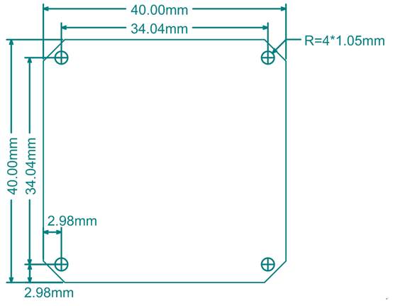
Figure 3 Mechanical Dimension