MT9J001/MT9J003 DVP Camera with USB2.0 Camera Shield Rev.E
1.Introduction
USB2.0 camera shield Rev.E is that it supports MIPI interface sensors without any MIPI adapter board. It has an onboard 16MByte hardware frame buffer and has overcome the bandwidth and dropping frames issue when using the software frame buffer scheme. In addition, the onboard frame buffer supports synchronized multiple cameras taking images exactly at the same time. It well supports both PC and an embedded system like Raspberry Pi, and also can provide customized support for Odroid, Beaglebone Black, Nvidia Jetson TK/TX boards.
Now we will introduce you to how to use the Arducam Shield development kit to evaluate MT9T001/MT9J003.
1.Hardware
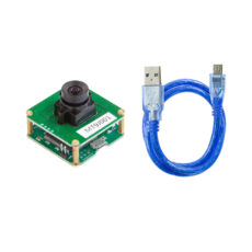
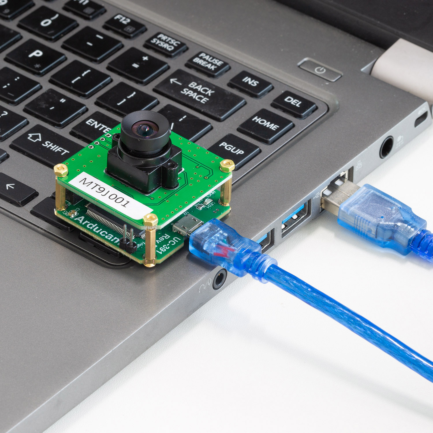
Usually, the delivery status same as the following figure. One end of the FPC cable is connected to the camera board, and the other end is connected to the shield(*15PIN*). You only need to use a Micro usb2.0 cable to connect the hamburger to your PC.
2.Software
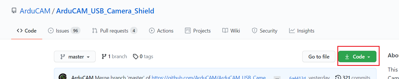
2.1 Download and unzip the Code Package
Click here to download the zip file.
2.2 Driver installation
For more information, you can go to the Doc.
- Plug the USB cable into the camera and the host PC USB port
- Go to Start -> Settings -> Control-Panel -> Device Manager, right-click the unknown device, and select “Update Driver Software”
- Right-click This PC and then click Manage to find the Device Manager under System Tools on Windows 10
- Select the “Browse my computer for driver software”
- Select “Let me pick from a list of device drivers on my computer”
- Select “Show All Devices”
- Press the “Have Disk” button
- Enter the path to the ArduCAM USB2 driver, where you save the downloaded file in ArduCAM_USB_Camera_Shield-master\Drivers
- Confirm the installation of the driver by pressing “Yes”
- Confirm the installation again by pressing “Install”
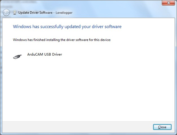
- You will successfully install the driver like this
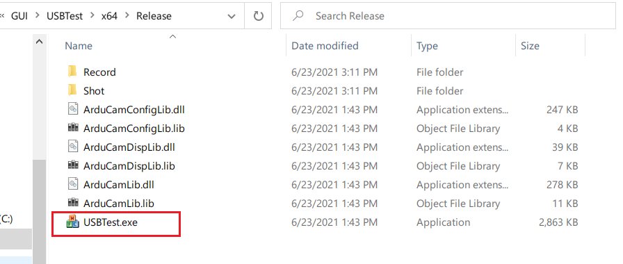
2.3 Run the USBTest.exe
Run the USBTest.exe in …\Release
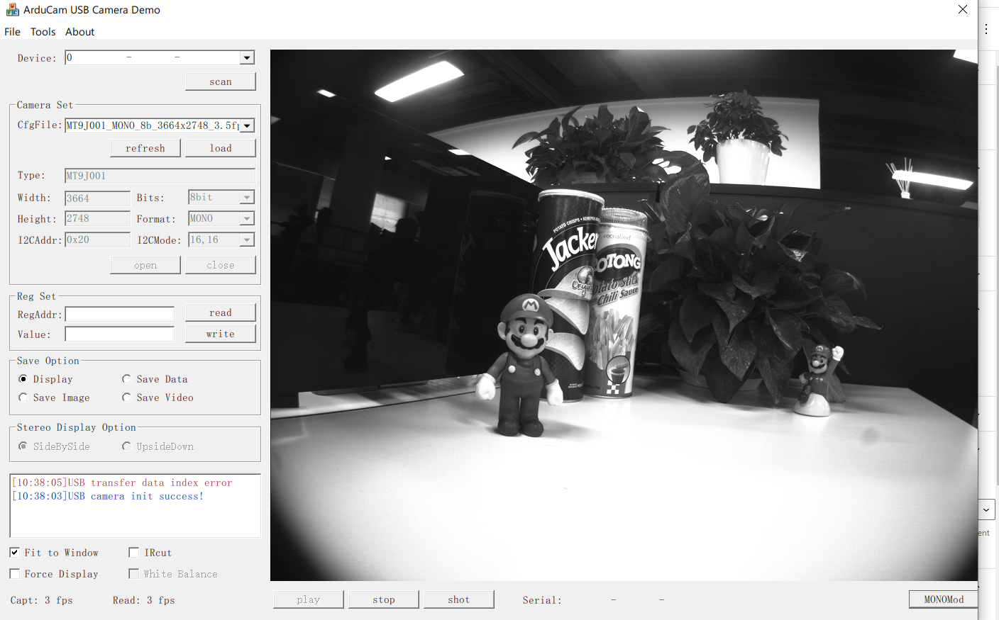
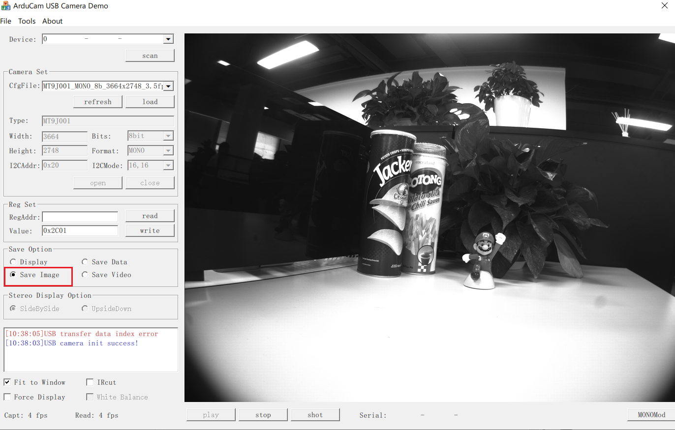
2.4 Set up on the Arducam USB Camera Demo and Preview the Image
- “Scan” the device
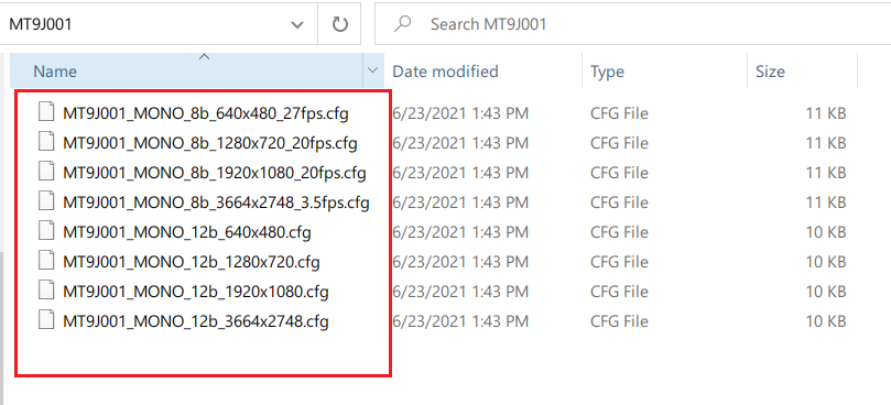
- “Select” and “load” the MT9J001 Configure file in ArduCAM_USB_Camera_Shield-master\Config\USB2.0_UC-391_Rev.E\DVP\MT9J001
- “Open” the MT9J001 Config File
- “Play” and you can see the preview
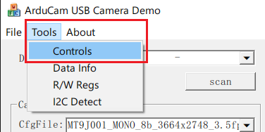
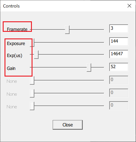
2.5 Adjust frame rate & exposure & gain
Tools->Controls
2.6 Read and Write the registers
- Single register can be read and written
Click the GIF image to see the Read and Write registers.
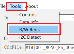
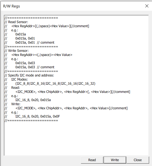
- Tools->R/W Regs(Batch read and write)
2.7 Capture single image
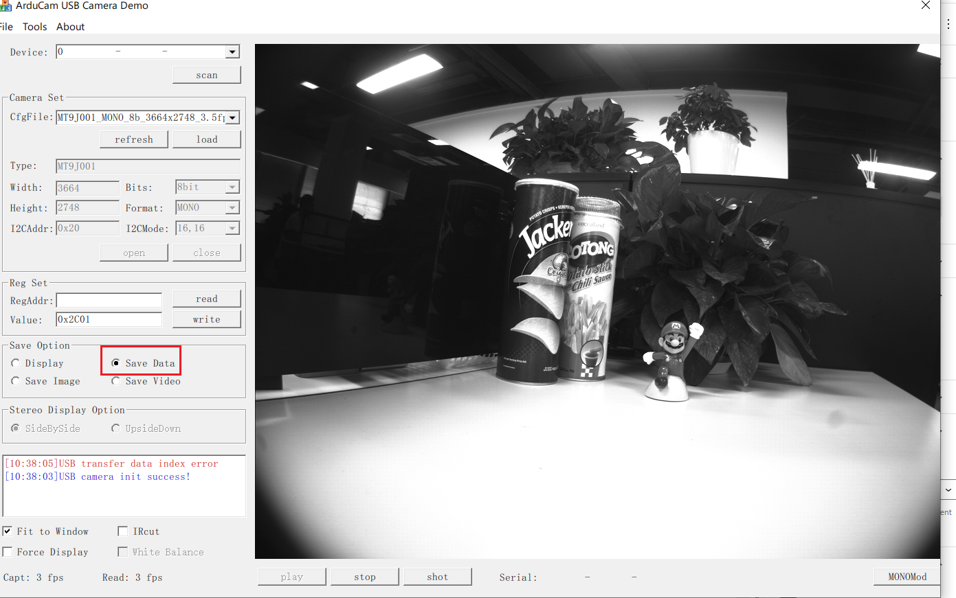
- Press shot and you can save single image as bmp format in ….\Release\shot

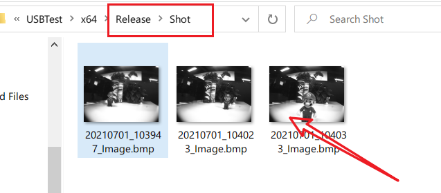
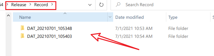
- Select Save data to continuous save images as raw format in …Release\Record
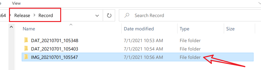
- Select Save Image to continuous save images as bmp format in …Release\Recode.
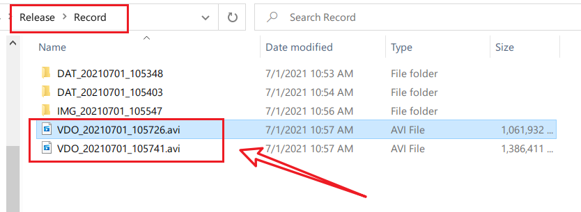
2.8 Capture and save video
- Select Save video to save video as .avi format in …Release\Record.

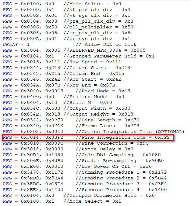
2.9 Modify the Configuration file
If some camera register values in the configuration file are not suitable, you can open the configuration file with a text editor to modify it. The following is the camera’s register. Refer to the existing format to modify the register value or add a register.