Quick Start
Note
The following applies to the Bullseye system.
General Hardware Connection
Warning
Cameras are sensitive to static. Earth yourself prior to handling the PCB.
A sink tap or similar should suffice if you don’t have an earthing strap.
Connection Details
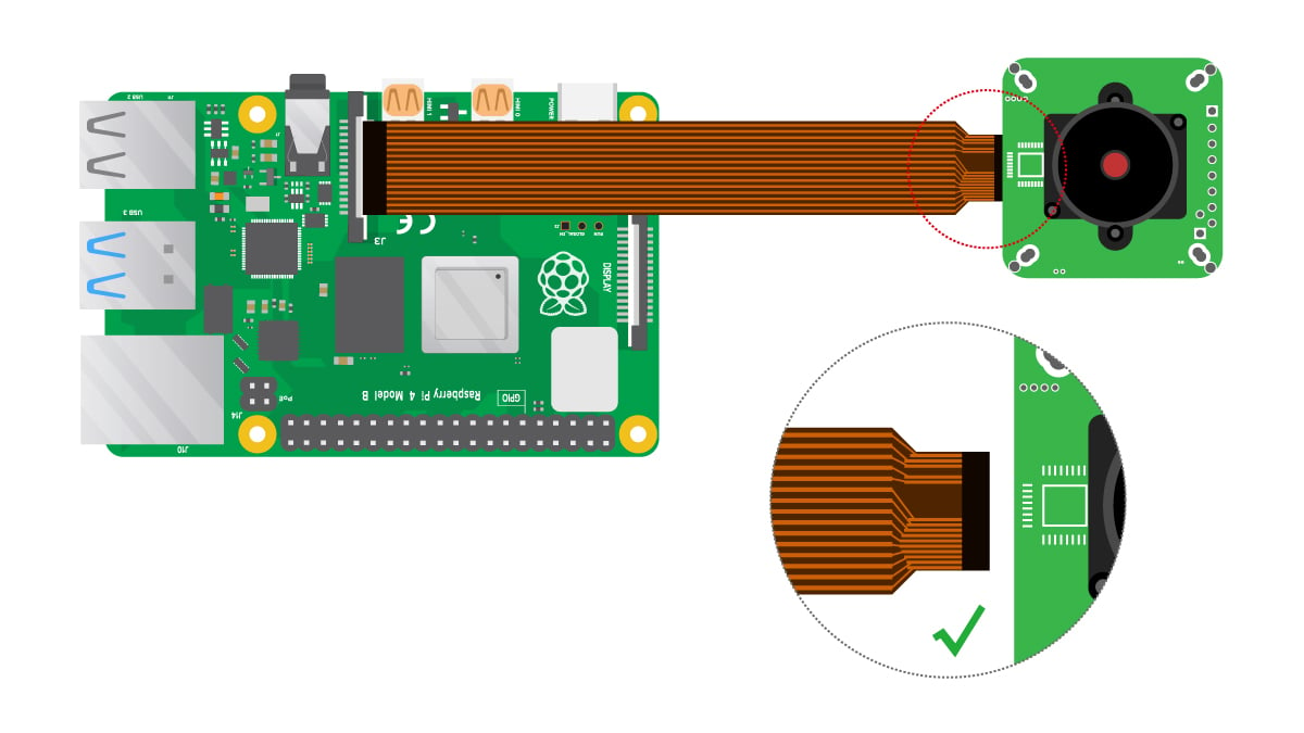
The Raspberry Pi and the camera module are connected using a flexible cable. The connection to the camera is called CSI interface and the connection to the Raspberry Pi is called MIPI interface.
-
Connect to Camera
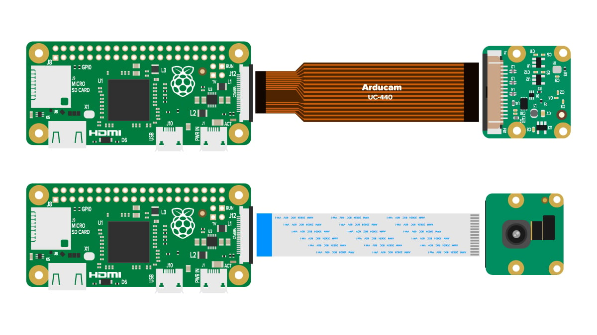
There are two different kinds of Raspberry Pi CSI camera connectors: 15-pin and 22-pin.
The silver contacts of the cable have different orientations when connecting to different cameras. For specific connection methods, please refer to the introduction on the product page of each camera.
-
Connect to Raspberry pi
Tip
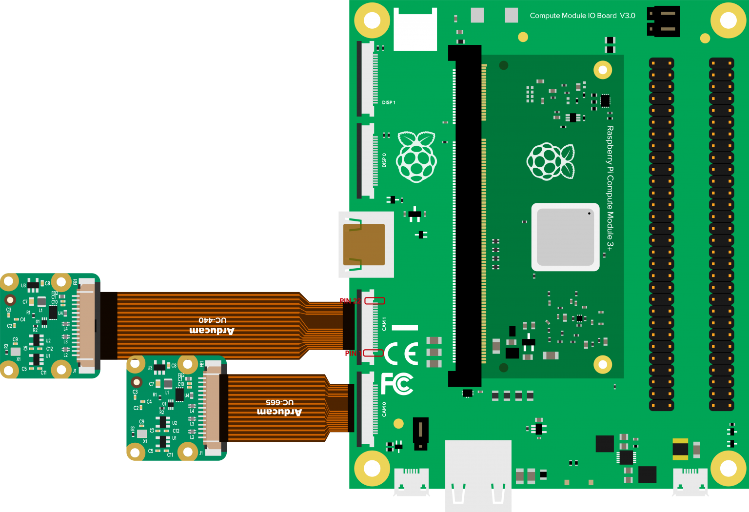
There are two different kinds of Raspberry Pi MIPI port connectors: 15-pin and 22-pin. The 15-pin connector is mostly seen on standard Raspberry Pi model; the 22-pin is on Raspberry Pi Zero-W and Compute Module IO Board.
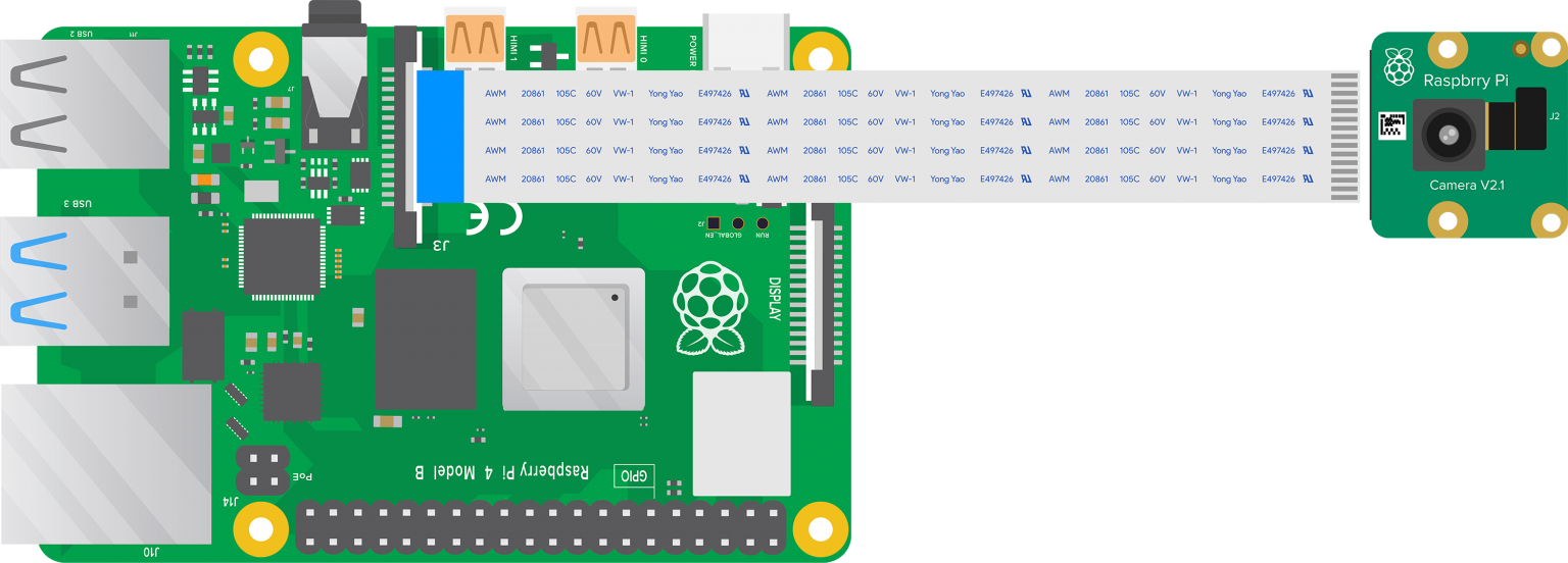
Plug the flex cable into the connector labeled CAMERA on the Raspberry Pi.
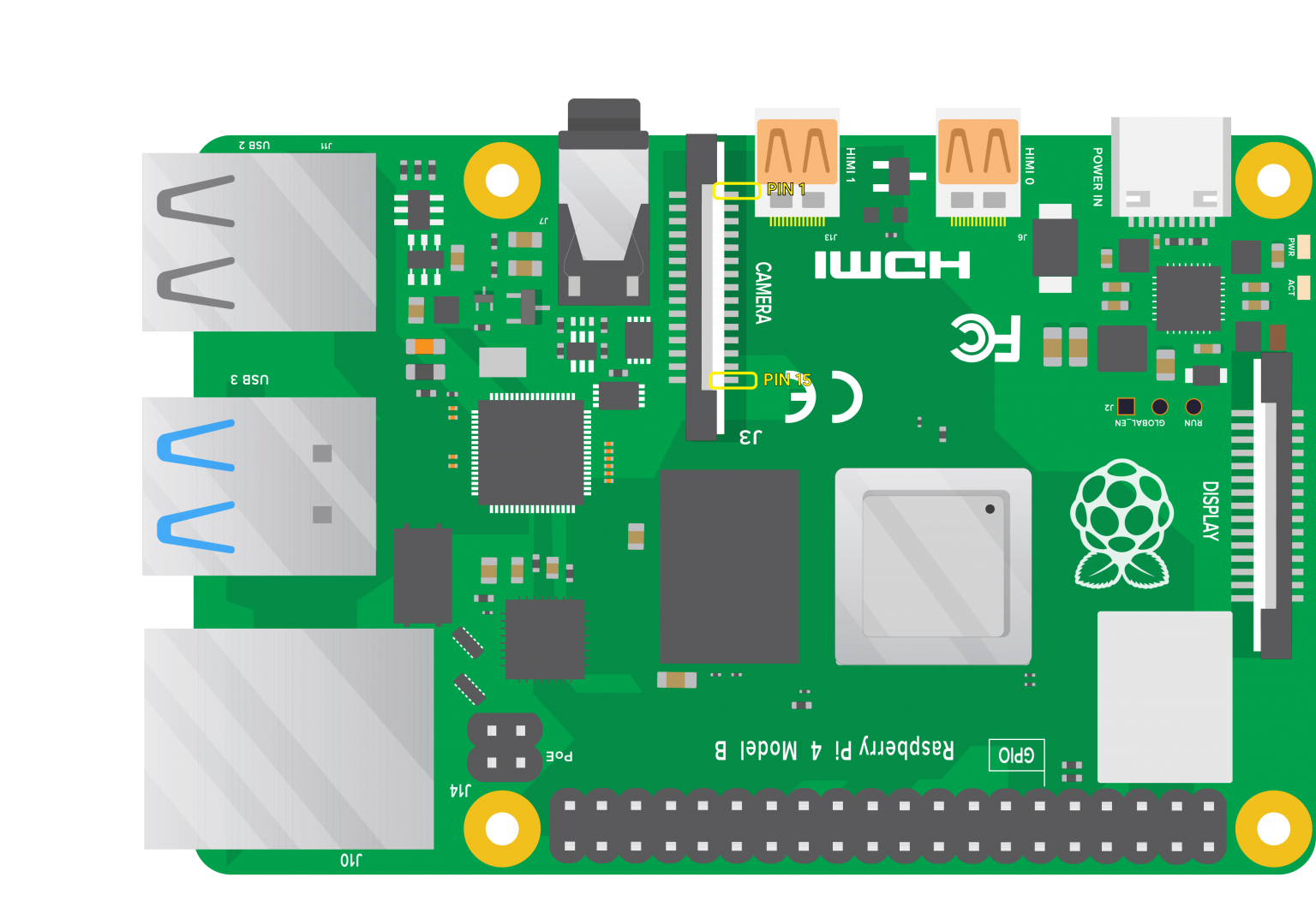
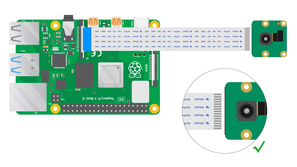
For Raspberry Pi 3-4:
The camera connector is between the Ethernet and HDMI ports. When plugging in the cable, the silver contacts must face the HDMI port.
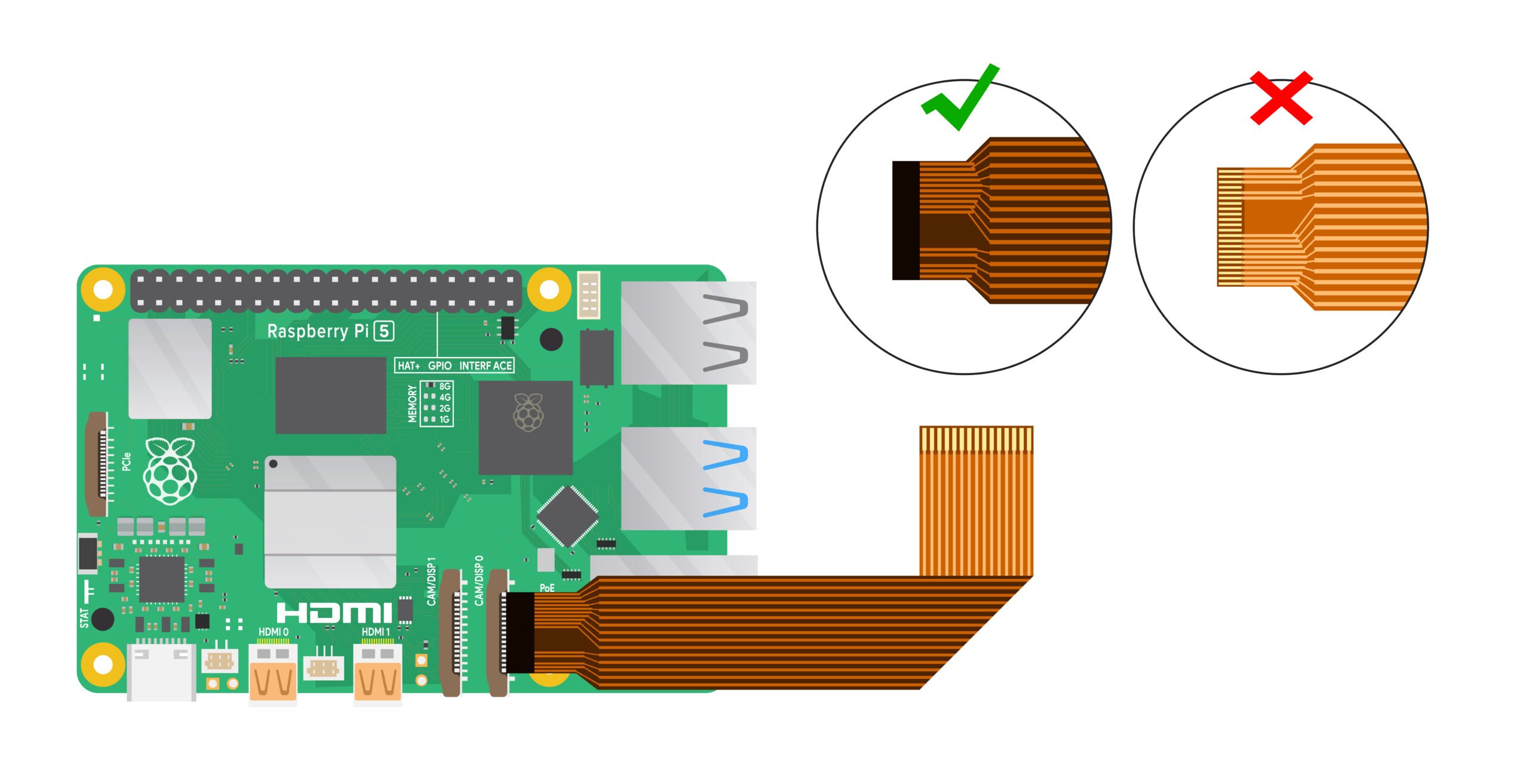
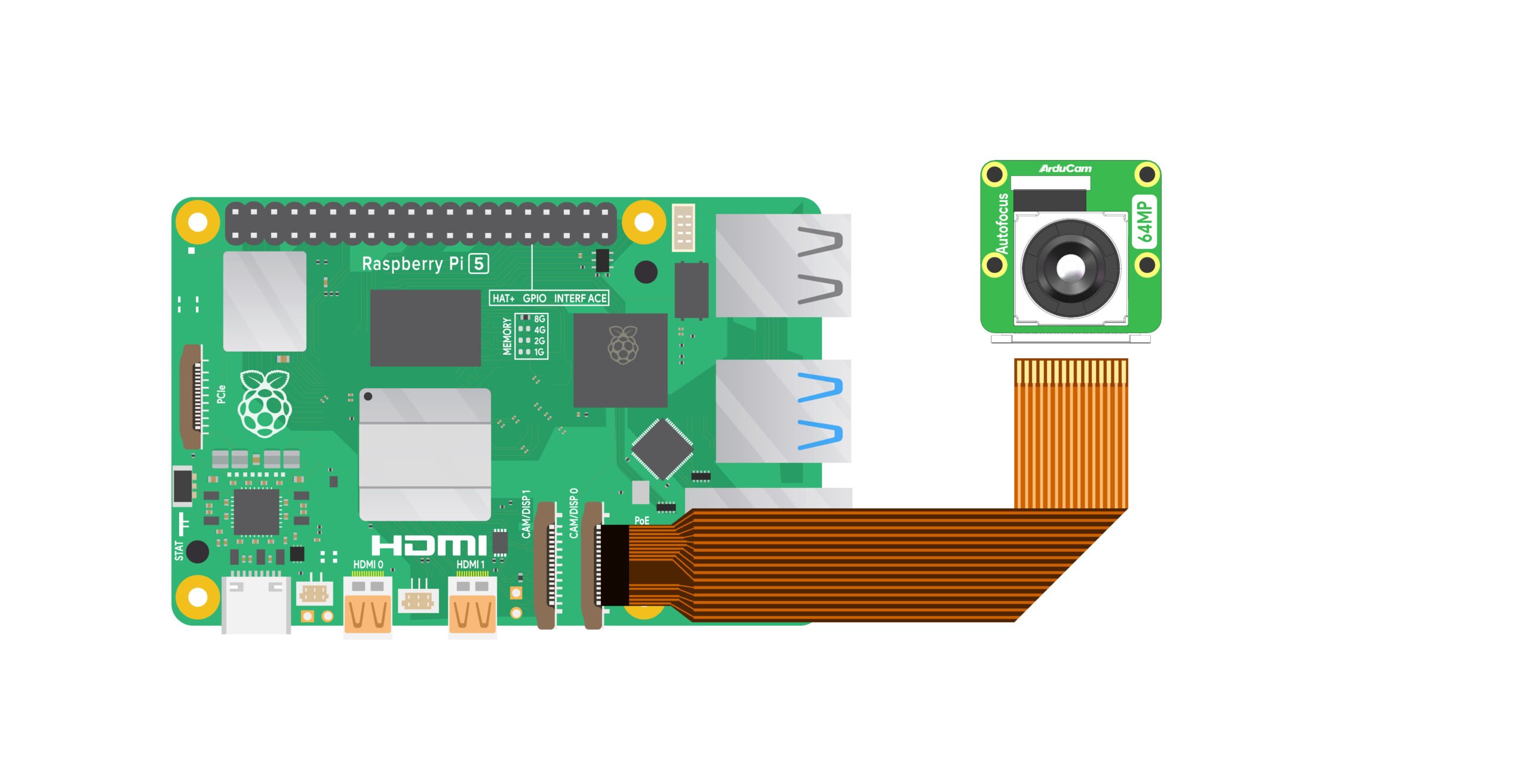
For Raspberry Pi 5:
The Raspberry Pi 5 has two camera connectors, both located between the Ethernet and HDMI ports. When you plug in the cable, the silver contacts face the Ethernet port.
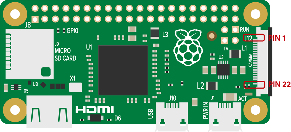
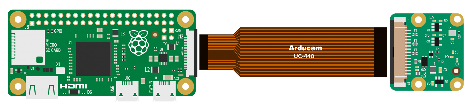
For Raspberry Pi Zero series and Compute Module:
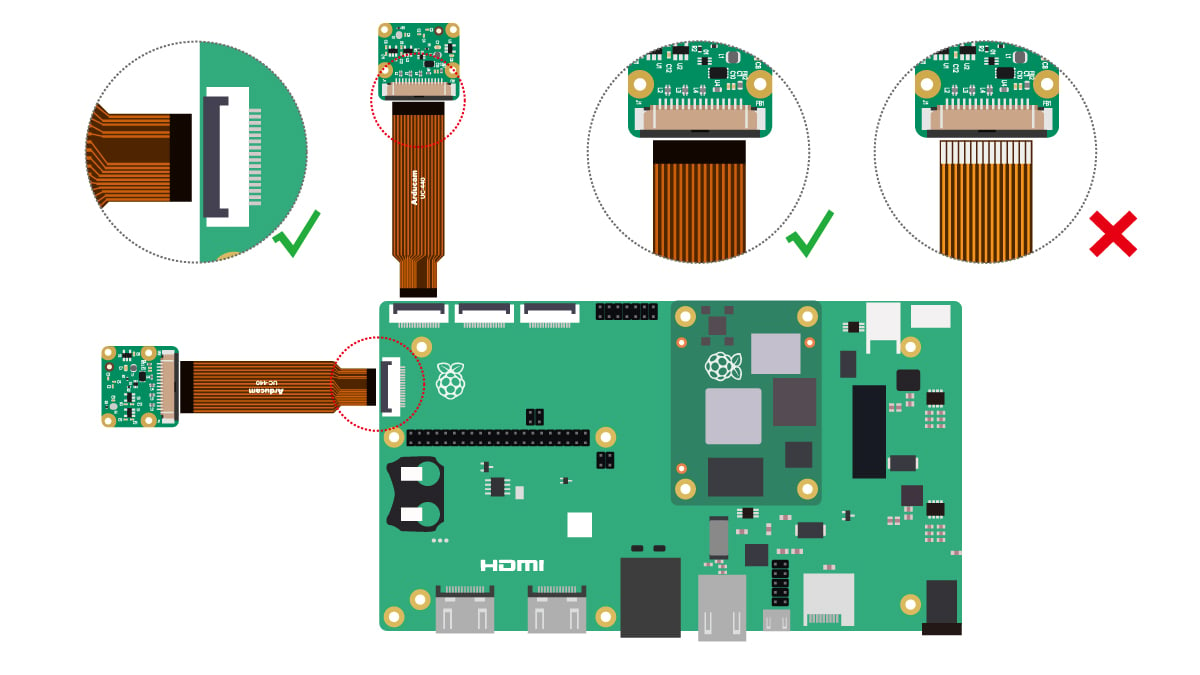
The camera connector is located on the side of the board at the interface labeled camera. When inserting the cable, the board should be facing up and the silver contacts should be facing down.
To open the connector, gently pull upward on the tab on the top of the connector. The flex cable should be inserted firmly into the connector, being careful not to bend the flex cable at too acute an angle. To close the connector, push the top part of the connector down while holding the flex cable in place.
Note
Since the camera board designs of different cameras are different, there are two connection methods on the camera side: the upper cable Pin port and the lower cable Pin port.
The camera-side cable connection methods in all the following pictures are for reference only. For specific camera-side connection methods, please refer to the detailed introduction on each product page.
- 15-22 pin on Pi5
(15pin-22pin FPC Cable)
- 15-15 pin and Pi3/Pi4
- 22pin and Pi Zero/ Pi Zero 2 W
- CM3/CM4
Connection schematic
Note
Since the camera board designs of different cameras are different, there are two connection methods on the camera side: the upper cable Pin port and the lower cable Pin port.
The camera-side cable connection methods in all the following pictures are for reference only. For specific camera-side connection methods, please refer to the detailed introduction on each product page.
- Pi5
- Pi3/Pi4
- Pi Zero/ Pi Zero 2 W
- CM3/CM4
Software Guide
Raspberry Pi Native Cameras
Tip
Please select the corresponding quick guide page below according to the camera you are using.
- Raspberry Pi Native Camera list:
| Resolution | Sensor |
|---|---|
| 5MP | OV5647 |
| 8MP | IMX219 |
| 12MP | IMX477 |
| 12MP | 477M |
| 12MP | IMX708 |
| 12MP | IMX378 |
| 16MP | IMX519 |
| 64MP | 64MP Hawkeye |
| 64MP | 64MP OV64A40 |
| 0.3MP | OV7251 |
| 1.58MP | IMX296 |
| 1MP | OV9281 |
| 2MP | OV2311 |
| 2MP | IMX290/IMX462/IMX327 |